Method and adaptively deriving exposure time and frame rate from image motion

a technology of image motion and exposure time, applied in the field of method and adaptive derivation of exposure time and frame rate from image motion, can solve the problems of inability to identify objects, loss of information that is generally not recoverable, and inability to accept smears of objects, etc., and achieve the effect of maximizing the signal-to-noise ratio (snr)

Inactive Publication Date: 2005-05-10
EXCELIS INC
View PDF10 Cites 56 Cited by
  • Summary
  • Abstract
  • Description
  • Claims
  • Application Information

AI Technical Summary

Benefits of technology

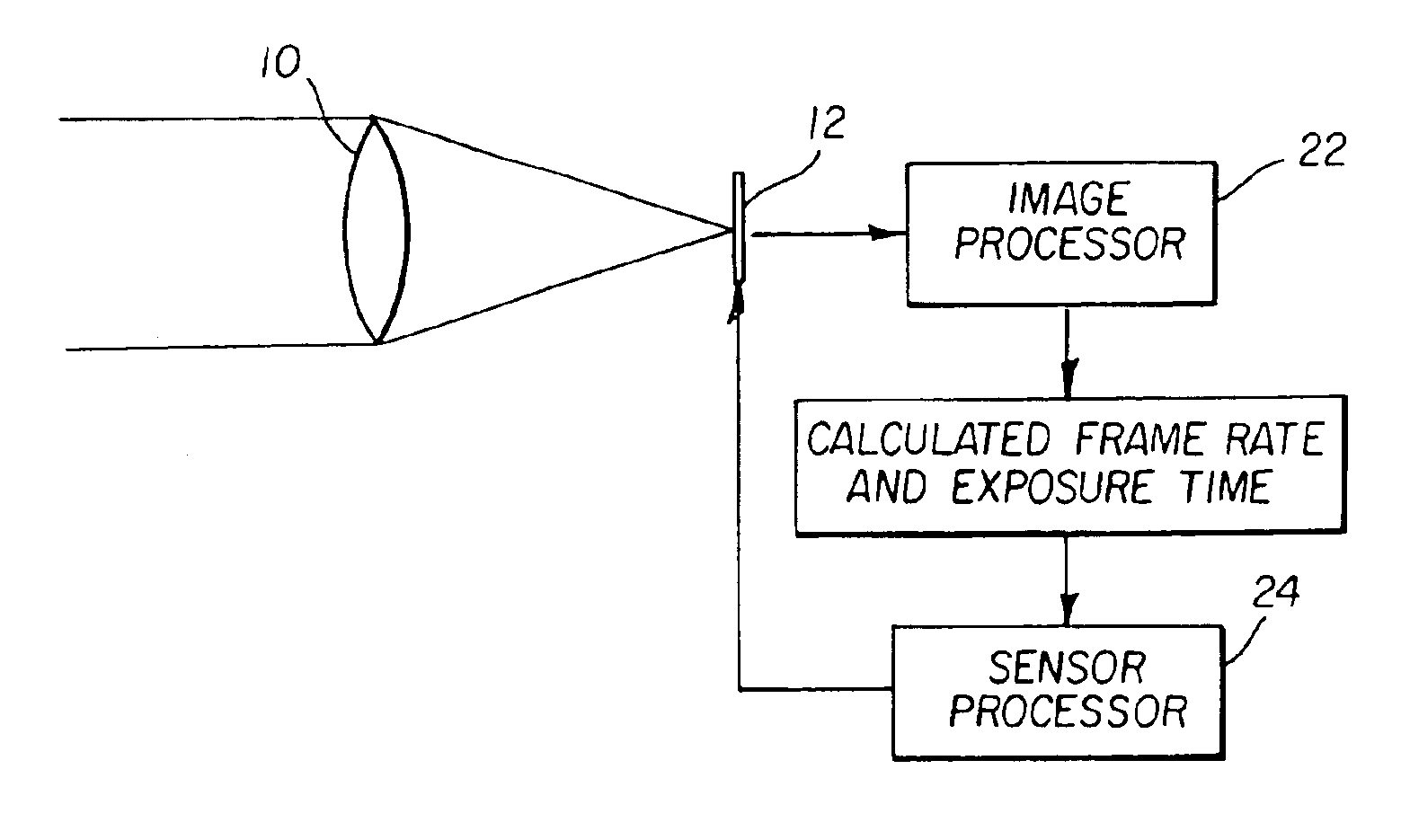
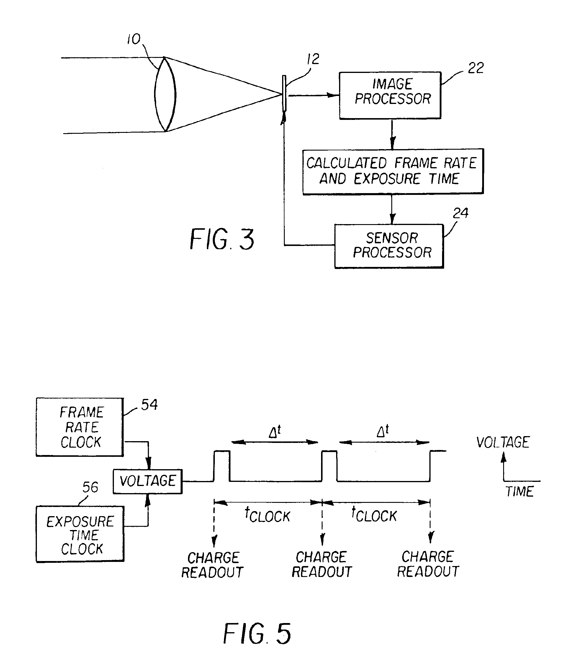
[0011]This invention allows the exposure time and frame rate for each frame of a video image capture system to be automatically determined. The exposure time is determined such that the signal-to-noise ratio (SNR) is maximized while keeping the motion blur from objects moving in the scene to a predetermined amount. The frame rate is determined such that the object displacement does not exceed a predetermined amount.

Problems solved by technology

Longer exposure times are desired to increase the SNR but may cause an unacceptable smear of the object.
If the smear is large enough, identification of the object may not be possible.
Motion smear above two pixels will cause a loss of information that is generally not recoverable.
Lower frame rates are desired to reduce the amount of image data that must be captured, disseminated, and stored, but may not capture enough frames of a fast moving object before it passes through the camera's FOV.
Unfortunately, it is not always convenient or even possible to have a high intensity flash source available while acquiring images.
For example, image capture systems used for remote sensing can not use a flash source.
Fast moving objects in the scene can still produce artifacts in the reproduced image.
The method proposed in U.S. Pat. No. 4,652,907 adaptively controls the parameters used in a recursive filter to sum the successive frames together to minimize the artifacts, but does not adaptively control the exposure time.
Another method proposed in U.S. Pat. No. 4,882,629 adaptively controls the exposure time based on the signal level, but does not account for the motion of objects in the scene.

Method used


Image

  • Method and adaptively deriving exposure time and frame rate from image motion
  • Method and adaptively deriving exposure time and frame rate from image motion
  • Method and adaptively deriving exposure time and frame rate from image motion

Examples


Embodiment Construction

[0017]Because image processing systems are well known, the present description will be directed in particular to attributes forming part of, or cooperating more directly with, the method in accordance with the present invention. Attributes not specifically shown or described herein may be selected from those known in the art. In the following description, a preferred embodiment of the present invention would ordinarily be implemented as a software program, although those skilled in the art will readily recognize that the equivalent of such software may also be constructed in hardware. Given the method as described according to the invention in the following materials, software not specifically shown, suggested or described herein that is useful for implementation of the invention is conventional and within the ordinary skill in such arts.

[0018]If the invention is implemented as a computer program, the program may be stored in conventional computer readable storage medium, which may ...


PUM


Abstract

In a method for determining the frame rate and exposure time for each frame of a video collection, an image capture system acquires at least two successive frames of a scene, separated in time. The two images are compared to determine if objects in the scene are in motion. If motion is detected, then the speed and displacement of the objects that are moving is determined. If the speed of the fastest moving object creates an unacceptable amount of image displacement, then the frame rate for the next frame is changed to one that produces an acceptable amount of image displacement. Also, if the speed of the fastest moving object creates an unacceptable amount of motion blur, then the exposure time for the next frame is changed to one that produces an acceptable amount of motion blur.

Description

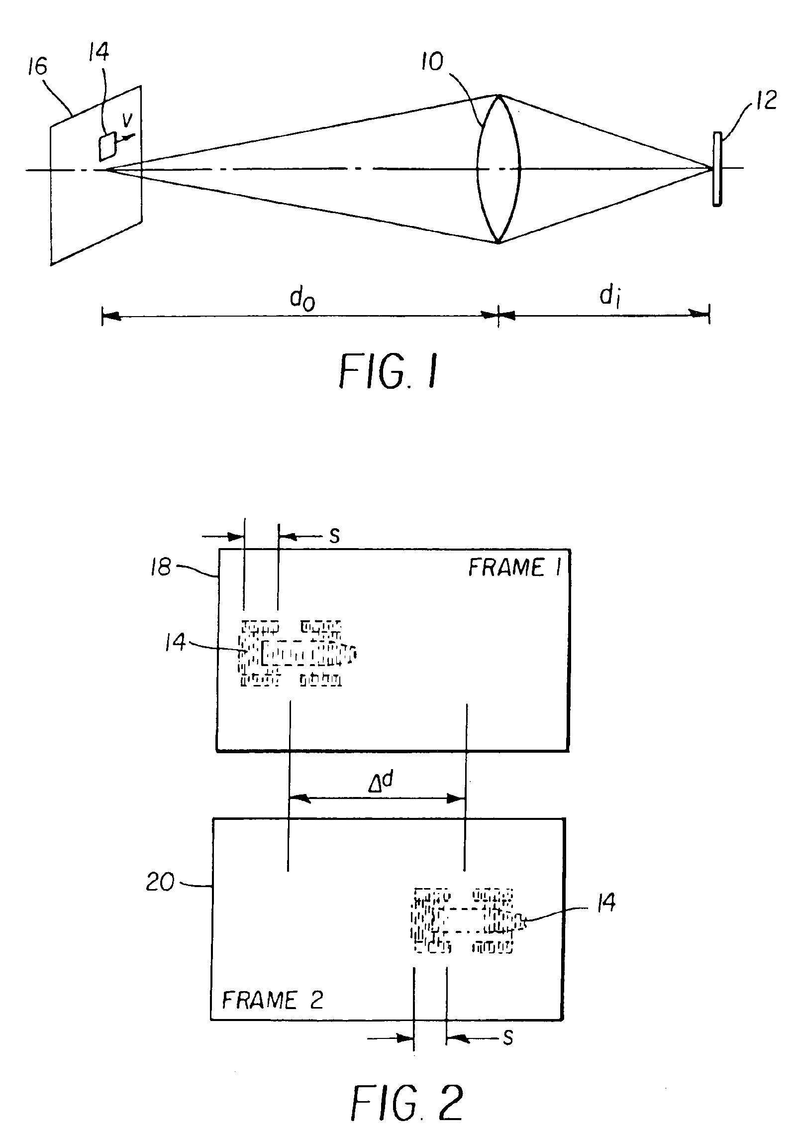
FIELD OF THE INVENTION[0001]The invention relates generally to a method for determining the exposure time and frame rate of an image capture system in order to minimize the motion blur between successive frames.BACKGROUND OF THE INVENTION[0002]FIG. 1 illustrates an image capture system, such as a camera, having an imaging lens 10 with a focal length f and an imaging sensor 12. An object 14 at a distance do in front of the camera will be properly focused at the imaging sensor 12 at a distance di behind the lens if the relationship between do, di and f is 1do+1di=1f.(1)If an object 14 is moving at a constant velocity v (m / s) within the field of view (FOV) 16 of the scene, and the exposure time of the image capture system is Δt, then the object will appear smeared in the image over a distance s, given by s=dido⁢v⁢ ⁢Δ⁢ ⁢t⁢ ⁢(meters).(2)If the imaging sensor 12 captures a digital image, then the object will be displaced by a distance s, measured in pixels, given by s=dido⁢p⁢v⁢ ⁢Δ⁢ ⁢t⁢ ⁢(...

Claims


Application Information

Patent Timeline
Patent Type & Authority Patents(United States)
IPC IPC(8): H04N5/235
CPCH04N5/2353H04N5/2351H04N23/71H04N23/73
Inventor TANTALO, THEODORE A.FIETE, ROBERT A.WARNER, FREDERICK J.
Owner EXCELIS INC
Why Eureka
Try Eureka