Real-time on-line sensing and control of mineral scale deposition from formation fluids

a technology of formation fluid and real-time online sensing, applied in the field of real-time online sensing and control of mineral scale deposition from formation fluid, can solve the problems of scale precipitation in the downstream of the well equipment and topside equipment of the well site, slow down, and equipment failure of the wellsi

Inactive Publication Date: 2005-05-10
BAKER HUGHES INC
View PDF19 Cites 14 Cited by
  • Summary
  • Abstract
  • Description
  • Claims
  • Application Information

AI Technical Summary

Benefits of technology

[0011]In another aspect, the present invention is a method for controlling mineral scale deposition from a formation fluid comprising: A) placing an optical probe having a probe surface which can measure changes in refractive index at the probe surface, into contact with a formation fluid produced or being produced from an oil well; B) measuring the changes in refractive index at the probe surface; C) determining the on-set and rate, if any, of mineral scale deposition from the formation fluid as a function of the changes in refractive index at the probe surface; D) comparing the rate, if any, of mineral scale deposition, to a predetermined range of acceptable mineral scale deposition; and E) effecting a change in the rate of addition, if any, to the formation fluid of an additive effective for preventing mineral scale deposition from a formation fluid; wherein: i) the probe surface which can be monitored for changes in refractive index is in contact with the formation fluid; ii) the

Problems solved by technology
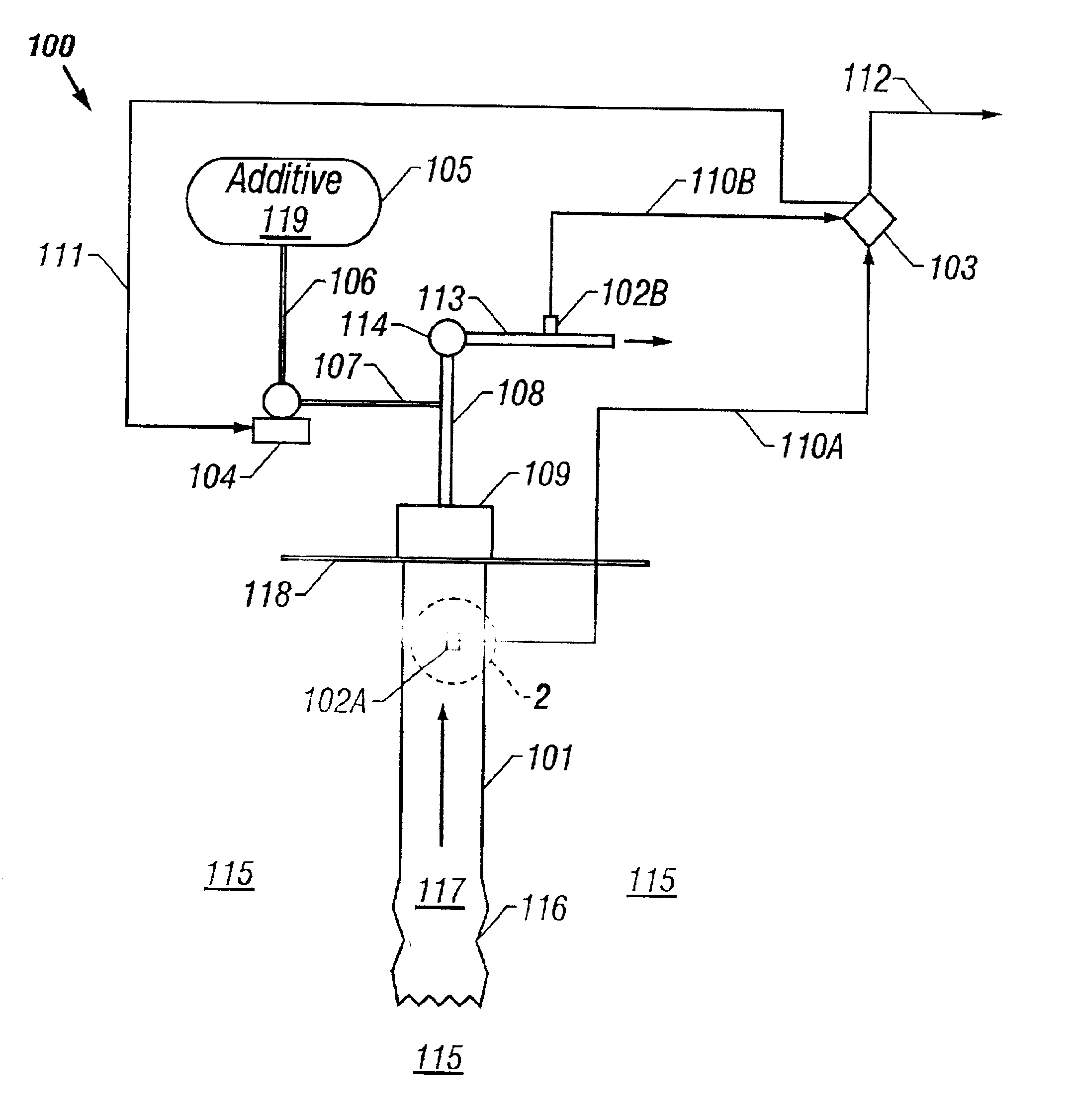
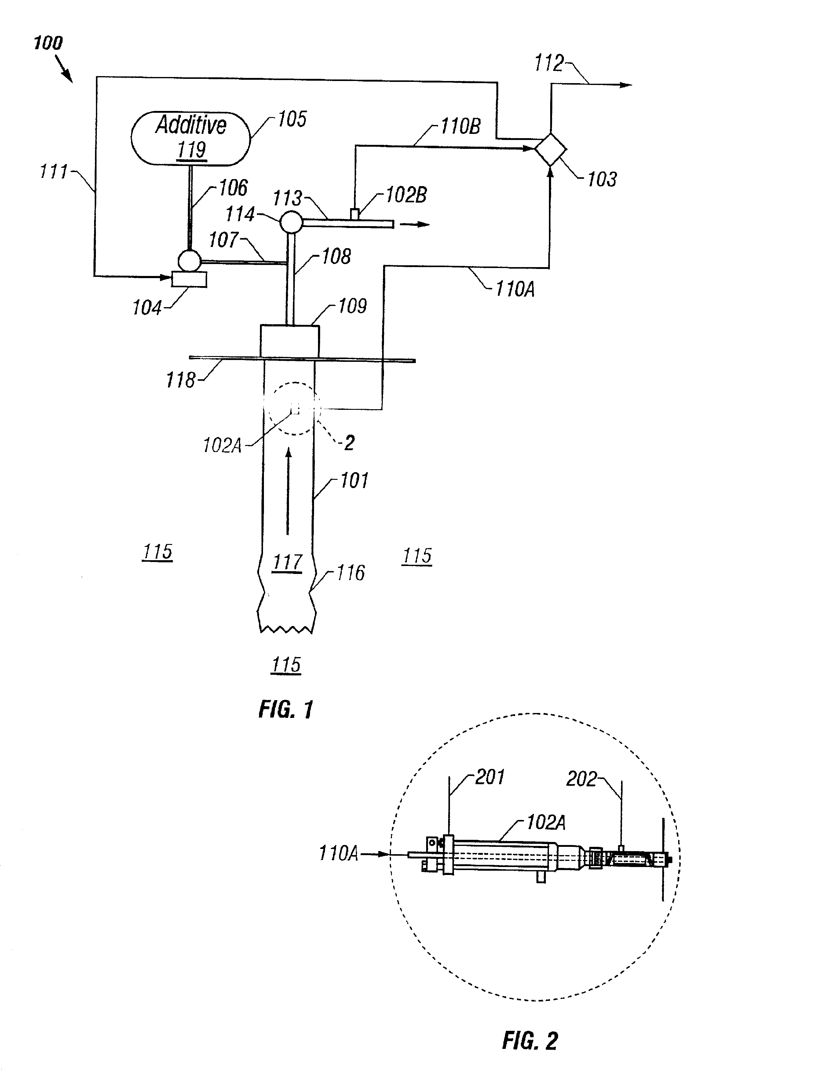
Specifically, well equipment in positions where incompatible water commingles and/or changes in these intrinsic physical properties occur is particularly vulnerable to scale precipitation.
It has also been recognized that well equipment and topside equipment downstream of these sites are also susceptible to scale precipitation in the well system.
Any mineral scale sticking to the well system surfaces may narrow pipes, and clog wellbor

Method used


Image

  • Real-time on-line sensing and control of mineral scale deposition from formation fluids
  • Real-time on-line sensing and control of mineral scale deposition from formation fluids
  • Real-time on-line sensing and control of mineral scale deposition from formation fluids

Examples


example 1

[0056]A brine composition is divided into anion (AW) brine and cation (CW) brine where each brine contains only the respective scaling ions and sodium chloride. The pH of the AW portion of the brine is adjusted using glacial acetic acid to reach the desired point. CW water is mixed and used without further modification. All experimental data is generated at standard temperature and pressure conditions. The wavelength used for this experiment is 660 nm. Data is collected for both the probe and dynamic scale testing apparatus and is stored and analyzed at a sampling rate of 1 sample / sec.

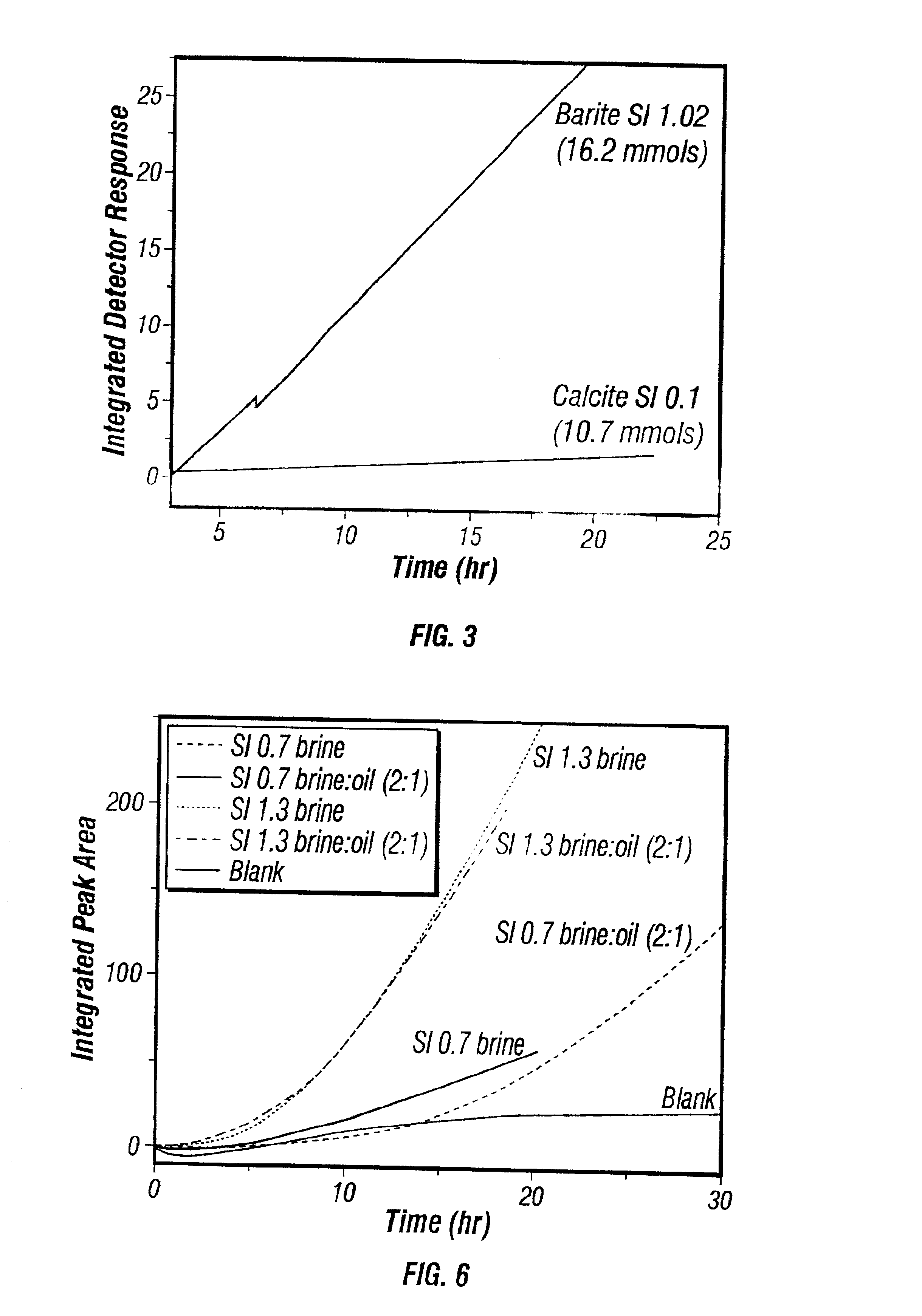
[0057]FIG. 3 represents laboratory measurements utilizing a UV / Vis spectrophotometer and a fiber-optic ATR probe with de-ionized water as a reference. The scaling rate is determined for two unique brine solutions containing 16.2 mmol / L barium sulfate and 10.7 mmol / L calcium carbonate, respectively. These probe response differences shown in FIG. 3 reveal the sensitivity of the probe to different types o...

example 2

[0060]FIG. 4 demonstrates the correlation between the detector response rate and different scale inhibitor effectiveness for a given calcium carbonate scaling brine. These experiments correlate pressure increase in a flow loop with probe response are performed by coupling a dynamic scale testing apparatus with the probe.

[0061]Peristaltic pumps operating at a combined flow rate of 600 mls / hr, each individually pumped AW and CW through stainless steel tubing which is submerged in a water bath. In the water bath, both fluid lines (AW and CW) are combined and flowed through an {fraction (1 / 16)}″ (16 mm) OD stainless steel tubing whose ID was 1.6 mm and length was 1 m. A pressure transducer is located upstream from the AW and CW mixing point to measure the absolute pressure increase resulting from scale precipitation plugging the flow line. The probe is placed at the outlet of the tubing wherein the combined AW and CW are flowed over the probe tip. The scale inhibitors shown in FIG. 4 ar...

example 3

[0063]Example 3 is performed substantially identically to Example 3 except that a single scale inhibitor is used at different concentrations.

[0064]The data for both the pressure and the probe response is displayed in FIG. 5.


PUM


Abstract

The present invention provides a method and system for controlling mineral scale deposition from a formation fluid. The rate at which scaling is occurring is measured in real time using an attenuated total reflectance probe and a photometer. The results are then used to determine whether to increase, decrease or leave unchanged addition of anti-scaling additives.

Description

BACKGROUND OF THE INVENTION[0001]1. Field of the Invention[0002]This invention relates to a method for use in oilfield and pipeline operations to monitor and control mineral scale precipitation from formation fluids. This invention particularly relates to a method for monitoring and controlling the deposition of mineral scale that is originating from formation fluids contained in wellbores, pipelines, and related equipment.[0003]2. Background of the Art[0004]Petroleum fluids primarily consist of oil and water and are herein referred to as formation fluids. A formation fluid may also contain oil and water insoluble compounds such as clay, silica, waxes, and asphaltenes, which exist as colloidal suspensions.[0005]In addition to the already listed components, formation fluids can also include inorganic components which can precipitate to form mineral scales. The process of mineral scale precipitation is known as scaling. Of primary concern to this invention are mineral scales and scali...

Claims


Application Information

Patent Timeline
IPC IPC(8): E21B37/06E21B37/00E21B47/00G01N21/55G01N21/43G01N21/41
CPCE21B37/06G01N21/552G01N21/431E21B47/00
Inventor SMITH, J. KEVYNMEANS, C. MITCHYUAN, MINGDONGPRZYBYLINSKI, JOHN L.LOPEZ, THOMAS H.PONSTINGL, MICHAEL JAMES
Owner BAKER HUGHES INC
Why Eureka
Try Eureka