Optical disk drive, its optical recording control method and data processing apparatus

a technology of optical recording control and optical disk drive, which is applied in the direction of digital signal error detection/correction, instruments, recording signal processing, etc., can solve the problems of poor quality optical media, which may be also commercially available, be used with optical disk drives, and opc error is more likely to occur, so as to make the start of recording reliable and the effect of high recording speed

Inactive Publication Date: 2005-05-10
RICOH KK
View PDF20 Cites 42 Cited by
  • Summary
  • Abstract
  • Description
  • Claims
  • Application Information

AI Technical Summary

Benefits of technology

[0013]An object of the present invention is to provide an improved optical disk drive in which the above-described problems are eliminated.
[0014]Another object of the present invention is to provide an optical disk drive which can appropriately determine the optimum recording power through the OPC prior to the recording of the optical disk based on the CAV method or the ZCLV method even when a poor-quality optical disk causing an OPC error is used, in order to make the starting of the recording operation at a high recording speed reliable.
[0015]Another object of the present invention is to provide an optical recording control method which controls an optical disk drive such that the optimum recording power can be appropriately determined through the OPC prior to the recording of the optical disk based on the CAV method or the ZCLV method even when a poor-quality optical disk causing an OPC error is used, in order to make the starting of the recording operation at a high recording speed reliable.
[0016]Another object of the present invention is to provide a data processing apparatus in which an optical disk drive is provided, the optical disk drive appropriately determining the optimum recording power through the OPC prior to the recording of the optical disk based on the CAV method or the ZCLV method even when a poor-quality optical disk causing an OPC error is used, in order to make the starting of the recording operation at a high recording speed reliable.
[0020]According to the optical disk drive of one preferred embodiment of the present invention, the OPC velocity changing unit changes a highest linear velocity of the linear velocities, provided for the disk rotation device, to a next highest linear velocity for the controlled velocity during a subsequent OPC. It is possible for the optical disk drive of the present invention to appropriately determine the optimum recording power through the OPC even when a poor-quality optical disk is used. The optical disk drive of the present invention is effective in making the starting of the recording operation at a high recording speed reliable.

Problems solved by technology

Although the development of optical disk drives with high recording linear velocity is put forward, there is the possibility that poor-quality optical media, which may be also commercially available, be used with the optical disk drives.
When the OPC is performed with the poor-quality optical disk at a high recording speed that is 16 times higher than the double speed (which ranges from 1.2 m / s to 1.4 m / s), the servo control of the PCA of the disk does not follow in accordance with the recording track and an OPC error is likely to occur.
In such a case, the OPC error is more likely to occur.
If an OPC error occurs, it is difficult for the conventional optical disk drive to determine the optimum recording power prior to the start of recording.
Hence, the conventional optical disk drive cannot start performing the recording of the optical disk because of the occurrence of an OPC error.
However, the conventional optical disk drive of the above document does not take into consideration countermeasures against an OPC error when the OPC is performed with a poor-quality optical disk at a high recording speed.
If the recording power is kept constant, the recording of information in the disk at the outermost track using the optimum recording power is impossible.
However, when using the laser diode of the optical pickup with its maximum output power being relatively low, or when using the poor-quality optical disk with a relatively low recording sensitivity, the optimum recording power that is determined through the OPC may exceed the maximum output power of the laser diode.
In such a case, the conventional optical disk drive cannot continue performing the recording operation of the optical disk at the high recording speed.

Method used


Image

  • Optical disk drive, its optical recording control method and data processing apparatus
  • Optical disk drive, its optical recording control method and data processing apparatus
  • Optical disk drive, its optical recording control method and data processing apparatus

Examples


Embodiment Construction

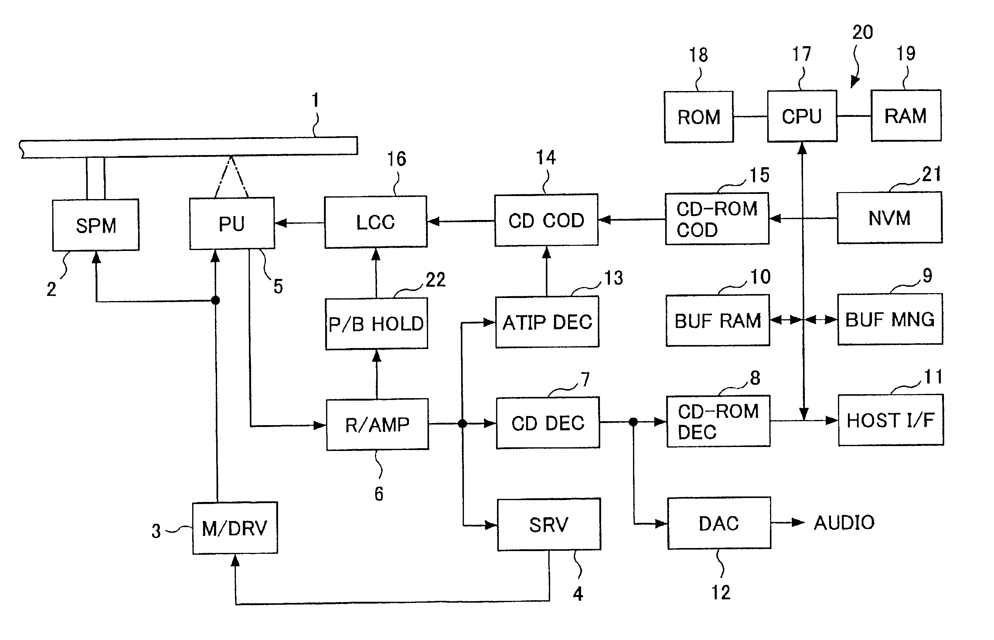
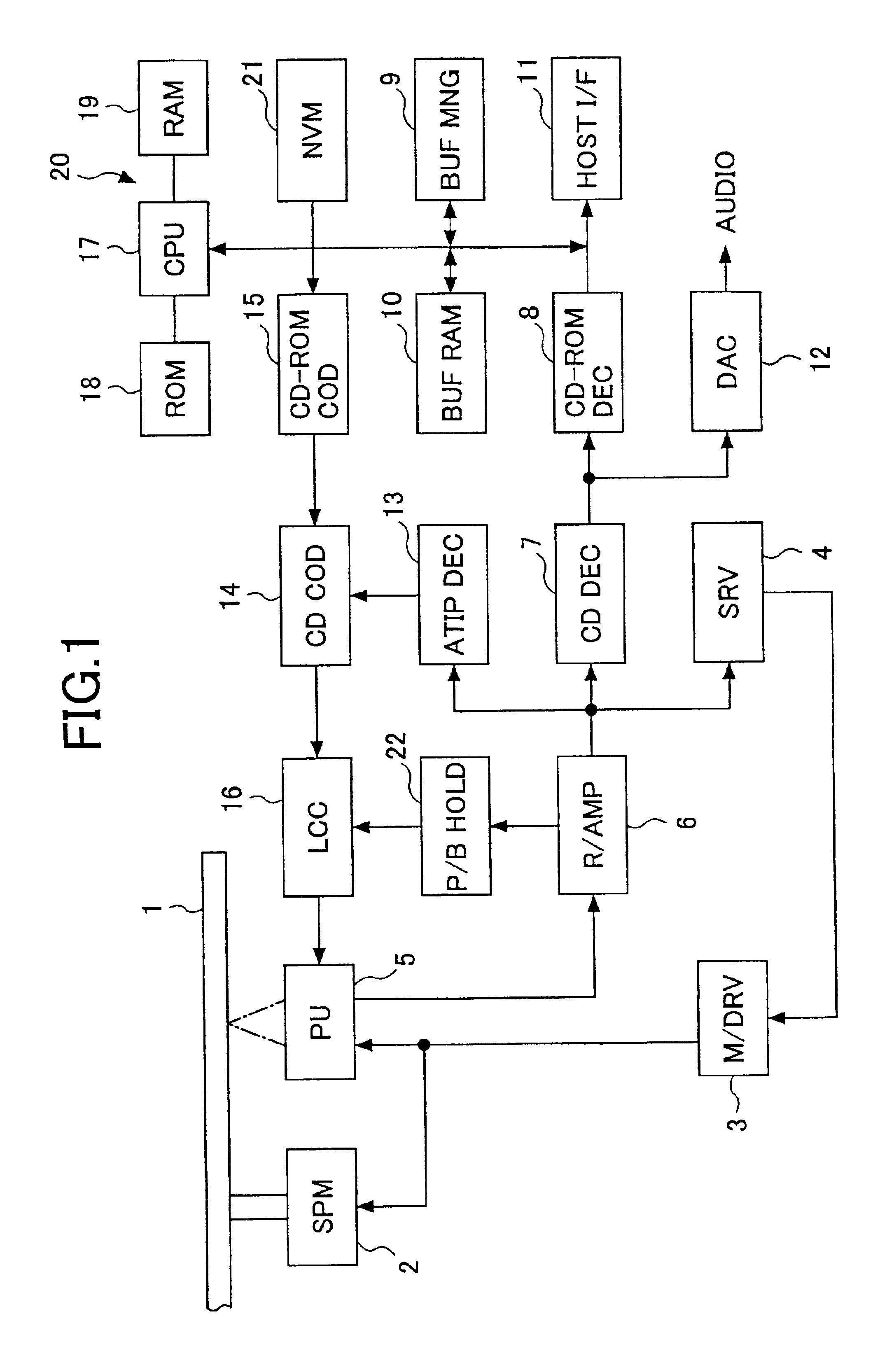
[0033]A description will now be given of preferred embodiments of the present invention with reference to the accompanying drawings.

[0034]FIG. 1 shows one preferred embodiment of the optical disk drive of the present invention. The optical disk drive of the present embodiment is configured into an optical disk recording / reproducing device that accesses CD-R as the optical disk 1.

[0035]In the optical disk drive of the present embodiment, the optical disk 1 is rotated by a spindle motor (SPM) 2. The rotation of the spindle motor 2 is controlled by a motor driver (M / DRV) 3 and a servo unit (SRV) 4 so that the disk 1 is rotated by the spindle motor 2 at a constant linear velocity (CLV) or a constant angular velocity (CAV). An optical pickup (PU) 5 includes a laser diode as the light source, an optical system, a focusing actuator, a tracking actuator, a photodetector, and a position sensor, which are not specifically shown in FIG. 1. The laser diode of the pickup 5 emits a laser light be...


PUM

PropertyMeasurementUnit
recording speedaaaaaaaaaa
linear velocityaaaaaaaaaa
velocityaaaaaaaaaa

Abstract

In an optical disk drive, an OPC is performed prior to a start of recording of an optical disk by accessing a power calibration area of the disk with a light beam emitted by a light source while the disk is rotated at a constant linear velocity. An optimum recording power for the light source during the recording is determined based on results of the OPC. A highest linear velocity of linear velocities is changed to a next highest linear velocity for a controlled velocity of a disk rotation device during a subsequent OPC. It is detected whether the OPC and the determination are normally performed after one of the linear velocities is set. The controlled velocity during the recording is set to an angular velocity corresponding to the one of the linear velocities at which the OPC and the determination are normally performed.

Description

BACKGROUND OF THE INVENTION[0001]1. Field of the Invention[0002]The present invention relates to an optical disk drive which accesses an optical disk, such as CD-R (compact disk-recordable) or CD-RW (compact disk-rewritable), an optical recording control method which controls the optical disk drive, and a data processing apparatus in which the optical disk drive is provided.[0003]2. Description of the Related Art[0004]Generally, the information on optical disks, such as CD (compact disk), is recorded along tracks, which may be concentric rings of a certain width provided for the innermost track to the outermost track. Typically, a track is a narrow annulus at some distance from the disk center. The track pitch is the center-to-center distance between neighboring tracks. The information is recorded on the optical disks, including CD-R (compact disk-recordable) and CD-RW (compact disk-rewritable), at a constant linear recording density.[0005]There are two major methods that carry out ...

Claims


Application Information

Patent Timeline
Patent Type & Authority Patents(United States)
IPC IPC(8): G11B7/125G11B7/00G11B19/28G11B7/0045G11B7/126
CPCG11B7/126
Inventor SATO, SHINICHI
Owner RICOH KK
Why Eureka
Try Eureka