
Laser amplifier system

a laser amplifier and amplifier technology, applied in gas laser construction details, laser details, active medium shape and construction, etc., can solve the problems of significant losses, increased cross section of the pump radiation field to be focused, and difficulty in achieving the highest possible pump power radiation density in the solid body. achieve the effect of optimal utilization

Inactive Publication Date: 2005-05-10
UNIV STUTTGART INST FUR STRAHLWERKZEUGE
View PDF9 Cites 25 Cited by
  • Summary
  • Abstract
  • Description
  • Claims
  • Application Information

AI Technical Summary

Benefits of technology

[0010]The advantage of the solution according to the invention is that it provides a straightforward way, with a deviating unit which deviates relative to a single symmetry plane, of in turn producing two different branches that enter the solid body from at least two different emerging branches of the pump radiation field.
[0012]The advantage of this solution according to the invention that is it provides a straightforward way of producing a large number of different focused branches that enter the solid body.
[0014]The advantage of this solution is likewise that it provides an extremely straightforward way of producing as many incident branches as possible.
[0016]This solution also has the advantage that it provides a particularly straightforward way of producing as large as possible a number of incident branches that are focused onto the solid body.
[0033]In terms of the specifics of the design of the focusing system, no detailed indications have been given in connection with the explanation of the individual exemplary embodiments so far. For instance, an advantageous solution provides for the focusing system to convert a branch that emerges from the solid body into an intermediate-collimated branch, and for it to convert the intermediate-collimated branch in turn into a branch that again enters the solid body and is focused onto it. This solution has the great advantage that precise imaging conditions can thereby be obtained and, in particular, the beam cross section does not experience any broadening in the course of the refocusing.
[0057]The advantage of this solution is that either two independent lasers can thereby be pumped with the same pump radiation field, or the possibility is provided of arranging the two solid bodies in such a way that they are used to amplify one laser radiation field passing through them, so that the pump radiation can be optimally utilized.

Problems solved by technology

The disadvantage of such a focusing system is that, with it, the cross section of the pump radiation field to be focused is always increased or significant losses arise because a part of the pump radiation field is not refocused back onto the solid body.
Overall, achieving the highest possible pump power radiation density in the solid body is problematic, especially under the premise that the greatest possible number of passes of the pump radiation field is striven for, since the absorption by the laser-active medium in the body during a single pass of the pump power is small.

Method used


Image

  • Laser amplifier system
  • Laser amplifier system
  • Laser amplifier system

Examples


Embodiment Construction

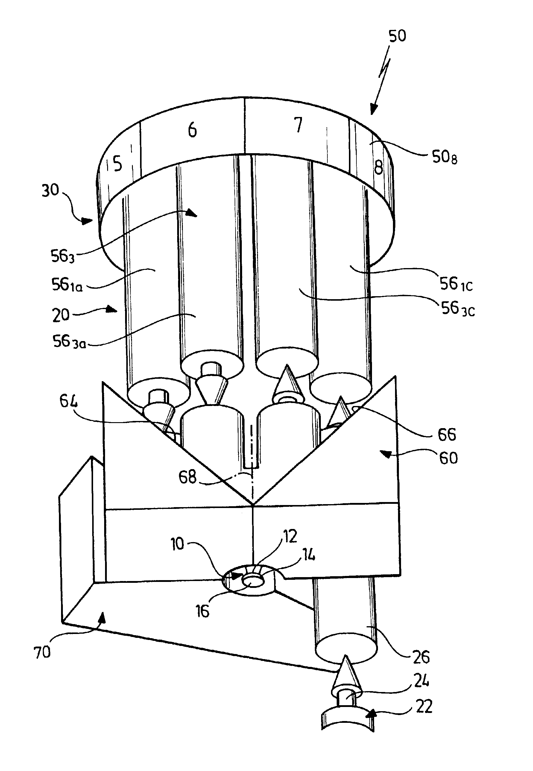
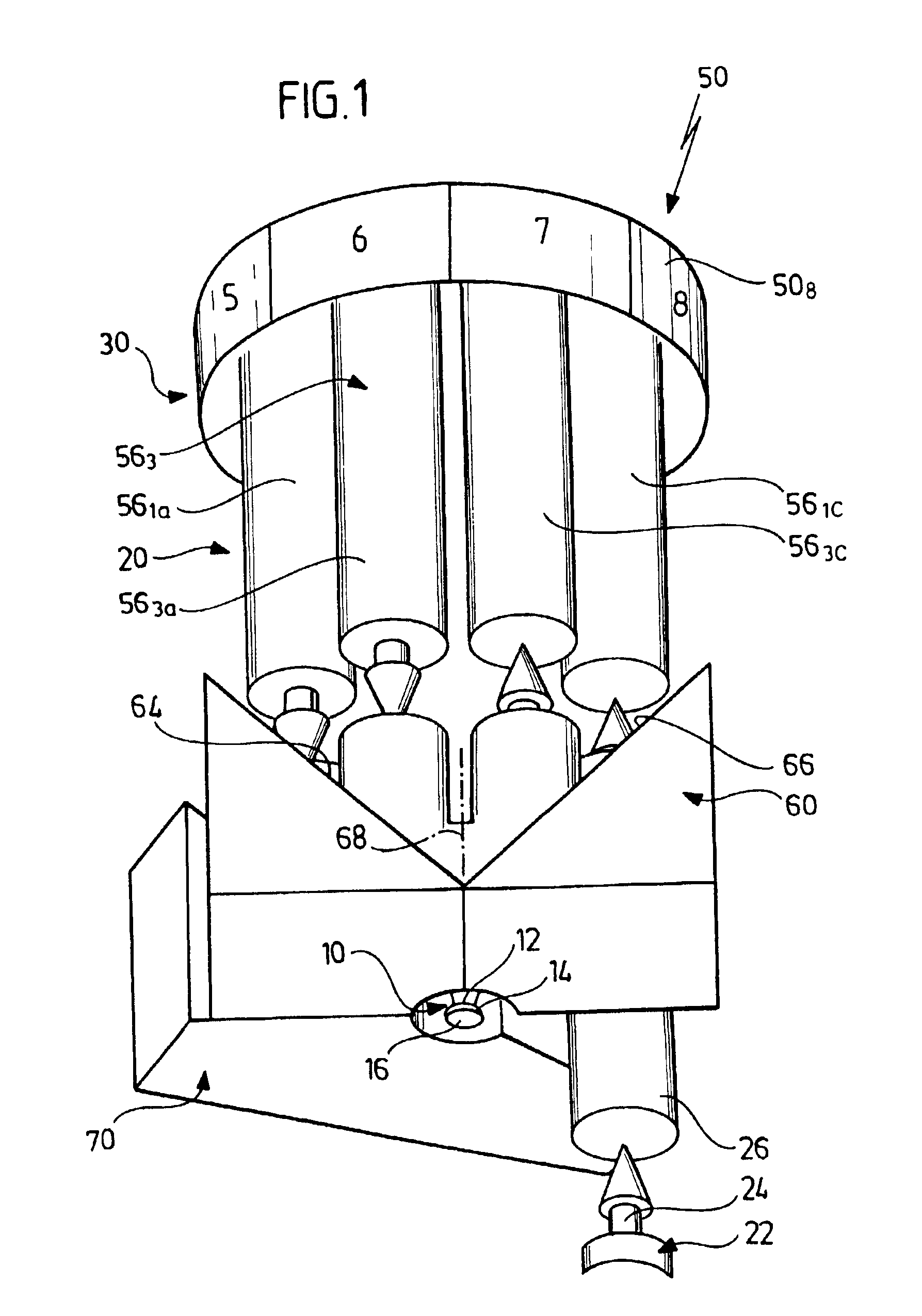
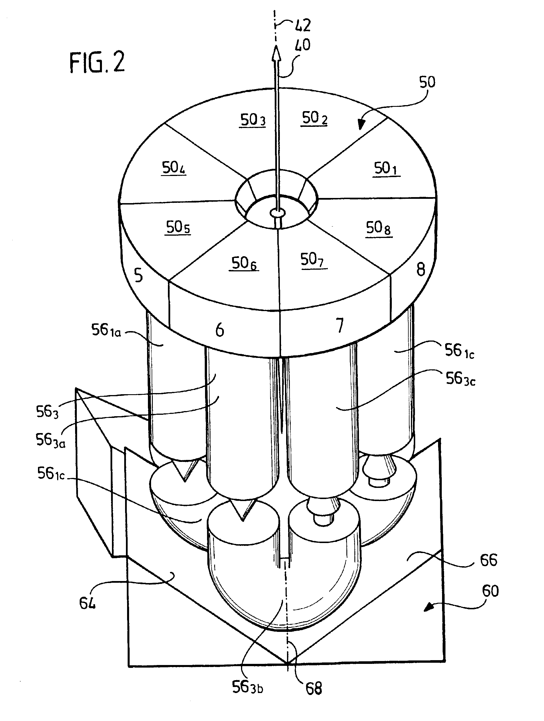
[0083]A first exemplary embodiment of a laser amplifier system according to the invention, represented in FIGS. 1 to 12, comprises a disk-shaped solid body 10 having a laser-active medium, which has a frontal flat side 12 and a rear flat side 14 that may be either plane or curved, and which rests via its rear flat side 14 on a reflector 16. Preferably, the reflector 16 is in this case applied to the rear flat side 14 as a layer.

[0084]Furthermore, the solid body 10 is preferably cooled via the reflector 16, and hence the rear flat side 14, such cooling being implementable, in particular, by using a cold finger on which the reflector 16 rests with thermal contact.

[0085]A pump radiation field, denoted as a whole by 20, which is defined by a focusing system, denoted as a whole by 30, and the reflector 16, is injected into the solid body 10 via the frontal flat side 12, and in this case passes multiply through the solid body 10, so that the laser-active medium in the solid body 10 can be...


PUM


Abstract

The invention relates to a laser amplifier system consisting of a solid body, which comprises a laser-active medium, of a pumping radiation source for generating a pumping radiation field, which repeatedly permeates the solid body, and of a focusing system. Said focusing system generates a number of different branches of the pumping radiation field that enter the solid body and converts at least one branch emerging from the solid body into one of the branches which enter the solid body and which are different from the emerging branch. The aim of the invention is to improve a laser amplifier system of the aforementioned type in order to be able to generate the highest possible pumping power density in the solid body while requiring the smallest possible amount of complexity. To this end, the focusing system comprises at least one deviating unit which converts, by deviating the radiation field with regard to a single plane of symmetry, at least two first partial branches formed from at least two different branches of the pumping radiation field emerging from the solid into at least two corresponding second partial branches which locally extend in a manner that is separate from the first partial branches and of which at least two branches entering the solid body are formed.

Description

[0001]This application is a continuation of international application number PCT / EP01 / 01129 filed on Feb. 2, 2001, which claims priority of German patent application no. 100 05 195 filed on Feb. 5, 2000.[0002]The present disclosure relates to the subject matter disclosed in PCT application No. PCT / EP01 / 01129 of Feb. 2, 2001, which is incorporated herein by reference in its entirety and for all purposes.BACKGROUND OF THE INVENTION[0003]The invention relates to a laser amplifier system comprising a solid body having a laser-active medium, a pump radiation source for producing a pump radiation field which passes multiply through the solid body, and a focusing system which produces a plurality of different branches of the pump radiation field that enter the solid body, and in this case converts at least one branch that emerges from the solid body into one of the branches that enter the solid body and are different from the emerging branch.[0004]Such a laser amplifier system is known fro...

Claims


Application Information

Patent Timeline
IPC IPC(8): H01S3/06H01S3/0941H01S3/081H01S3/0933
CPCH01S3/0604H01S3/09415H01S3/094084
Inventor ERHARD, STEFFENGIESEN, ADOLFSTEWEN, CHRISTIAN
Owner UNIV STUTTGART INST FUR STRAHLWERKZEUGE
Learn More