Portable radio system and portable radio equipment to be used in the same and frequency error prediction method used therefor

a portable radio and frequency error prediction technology, applied in the field of portable radio systems and portable radio equipment, can solve the problems of reducing the cordic number, reducing the error in derivation of phase shift, and reducing frequency detection error, so as to achieve small frequency error, low cost, and large

Inactive Publication Date: 2005-05-10
LENOVO INNOVATIONS LTD HONG KONG
View PDF23 Cites 7 Cited by
  • Summary
  • Abstract
  • Description
  • Claims
  • Application Information

AI Technical Summary

Benefits of technology

[0113]Therefore, utilizing original nature of the automatic frequency control, in that the frequency shift becomes smaller by feeding back the frequency error, the interval of two signals to be used for frequency error detection if the frequency error is large, and is set longer when the frequency error becomes smaller. By this, the frequency error can be made small with smaller tap number, and it can be adapted to large frequency error. By this, the equipment achieving low cost and low power consumption can be realized. It should be noted that the accuracy of frequency of the base station is strictly defined, frequency shift between a plurality of base stations is small so as not to influence for control.

Problems solved by technology

When a phase calculator such as CORDIC or the like is employed in the radio mobile equipment, tap number of CORDIC is reduced, and error may be caused in derivation of the phase shift.
Therefore, if the interval of the symbols becomes long, the frequency detection error becomes smaller even when the phase detection error is constant.
However, if the interval is initially set long, when the frequency error is sufficiently large and the absolute value of the phase shift becomes greater than π, correct frequency error cannot be detected.

Method used


Image

  • Portable radio system and portable radio equipment to be used in the same and frequency error prediction method used therefor
  • Portable radio system and portable radio equipment to be used in the same and frequency error prediction method used therefor
  • Portable radio system and portable radio equipment to be used in the same and frequency error prediction method used therefor

Examples


Embodiment Construction

[0123]The present invention will be discussed hereinafter in detail in terms of the preferred embodiments of a portable radio system according to the present invention with reference to the accompanying drawings. In the following description, numerous specific details are set forth in order to provide a thorough understanding of the present invention. It will be obvious, however, to those skilled in the art that the present invention may be practiced without these specific detailed.

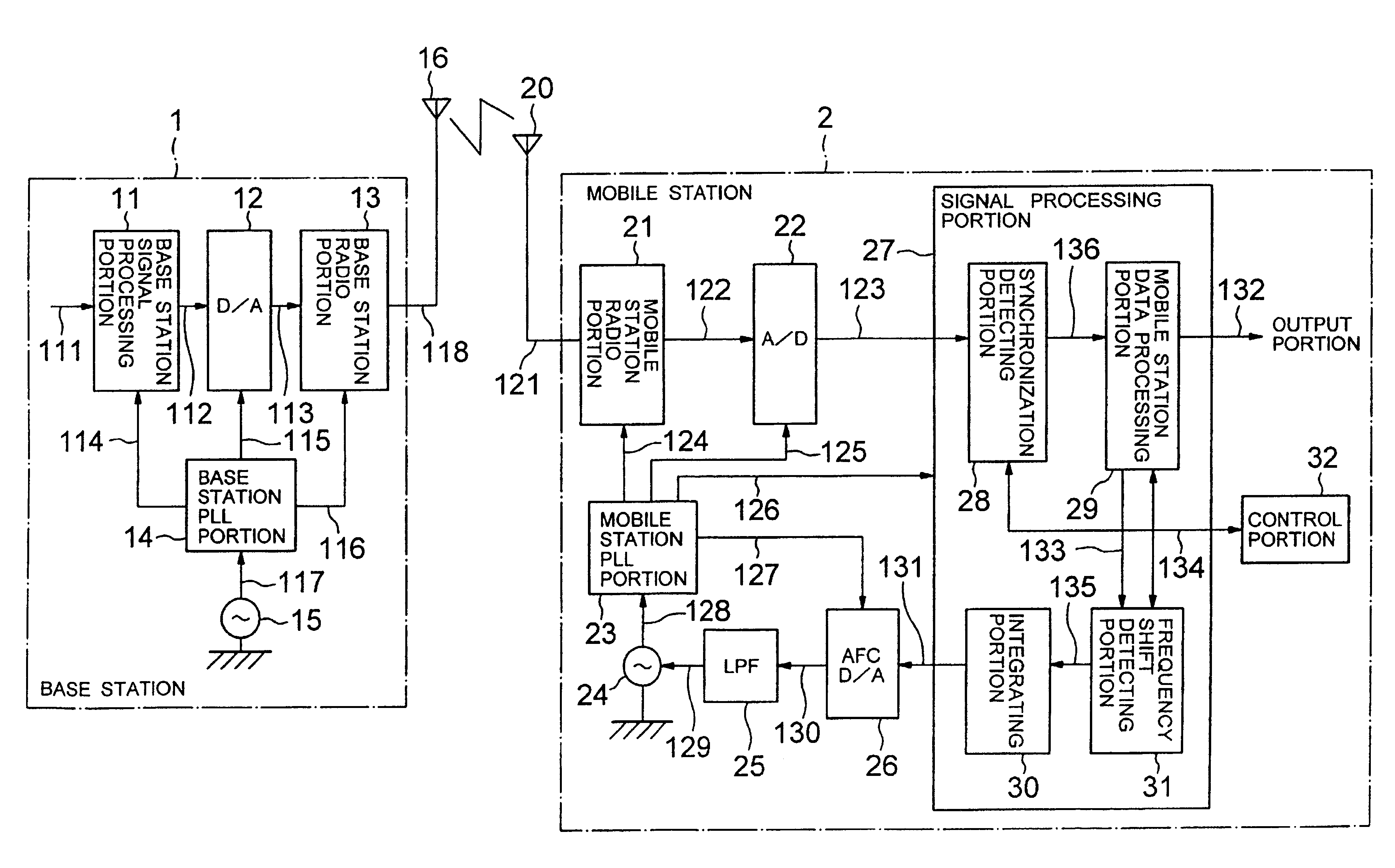
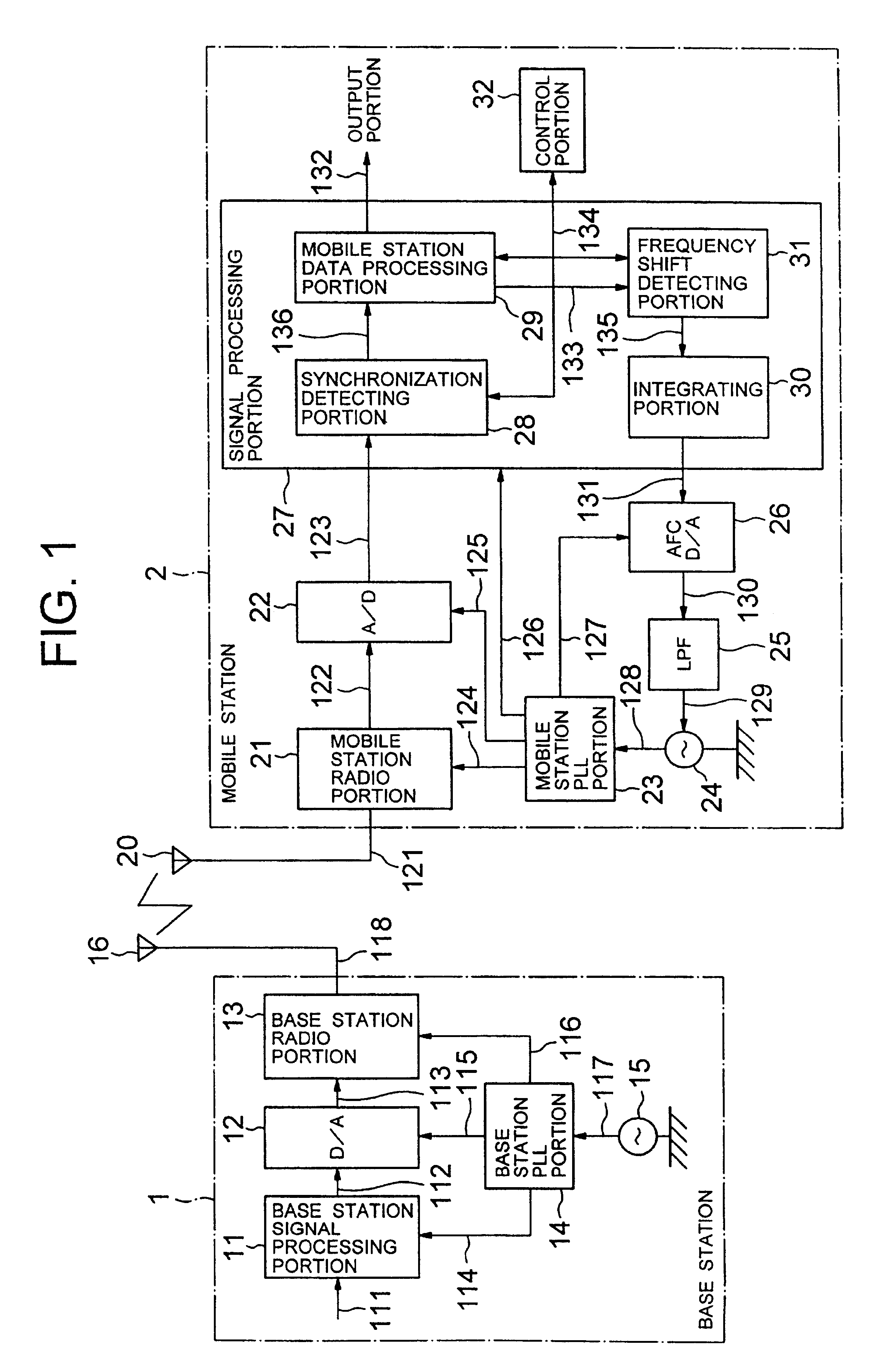
[0124]FIG. 1 is a block diagram showing a construction of one embodiment of a portable radio system according to the present invention. In FIG. 1, one embodiment of the portable radio system according to the present invention is generally constructed with a base station 1 and a mobile station 2.

[0125]The base station 1 is constructed with a base station signal processing portion 11, D / A (digital-to-analog) converter 12, a base station radio portion, a base station PLL (Phase Locked Loop) portion 14, a bas...


PUM


Abstract

A portable radio system, a portable radio equipment to be used in the same and a frequency error prediction method can be adapted to large frequency error by making tap number smaller and frequency error smaller. The portable radio system employs an automatic frequency control for detecting a frequency shift of an internal oscillator of a portable radio equipment with reference to a received wave transmitted from a base station having higher precision of frequency and adjusting the frequency of the internal oscillator by feeding back the frequency shift to the internal oscillator. Coordinate rotation digital computation (CORDIC) is employed for calculation of arctangent in the automatic frequency control.

Description

BACKGROUND OF THE INVENTION[0001]1. Field of the Invention[0002]The present invention relates generally to a portable radio system, a portable radio equipment to be used in the same, and a frequency error prediction method to be used therefor. More particularly, the invention relates to a frequency error prediction method in an automatic frequency control (AFC) of a portable radio equipment.[0003]2. Description of the Related Art[0004]In a portable radio equipment (mobile station) as a portable telephone or cellular phone of a system employing QPSK (Quadrature Phase Shift Keying) or WCDMA (Wideband Code Division Multiple Access), as a internal oscillator (mobile station oscillator) of the equipment, oscillators which are inexpensive and lower precision are frequently used for lowering cost.[0005]Therefore, in the mobile station, a frequency shift of the internal oscillator is detected with reference to a reception wave transmitted from a base station having high frequency precision ...

Claims


Application Information

Patent Timeline
Patent Type & Authority Patents(United States)
IPC IPC(8): H03J7/02H03J7/04H04L7/02H04L27/22
CPCH03J7/04
Inventor MATSU MOTO, MARIKOONO, SHIGERU
Owner LENOVO INNOVATIONS LTD HONG KONG
Why Eureka
Try Eureka