Absorbing rod, an apparatus for inserting the absorbing rod, a cask, and a method of storing spent fuel assemblies

a technology of absorbing rod and cask, which is applied in the direction of nuclear engineering, greenhouse gas reduction, nuclear elements, etc., can solve the problems of poor accommodation efficiency of spent fuel in the cask, complicated plate or square pipe formation, and high labor intensity, and achieve the effect of shortening the distance dd and increasing the accommodation density of spent fuel assemblies

Inactive Publication Date: 2005-05-10
MITSUBISHI HEAVY IND LTD
View PDF11 Cites 15 Cited by
  • Summary
  • Abstract
  • Description
  • Claims
  • Application Information

AI Technical Summary

Benefits of technology

[0018]It is an object of the present invention to provide an absorbing rod capable of heightening the accommodation density of spent fuel assemblies, by effectively utilizing the control rod inserting space and measuring rod inserting space existing in the spent fuel assemblies for PWR and shortening the distance dd for assuring the subcriticality among the spent fuel assemblies, its inserting apparatus, cask, and conveying and storing method of spent fuel assemblies.
[0020]The absorbing rod according to another aspect of this invention is made of aluminum composite material or aluminum alloy formed by adding powder of boron or boron compound having a neutron absorbing performance to aluminum or aluminum alloy powder. Since the absorbing rod is made of such material, it is not damaged by minor shocks during transportation. As a consequence, it is possible to maintain the neutron absorbing ability even during transport. For example, it is much safer and therefore preferable to an absorbing rod having a structure in which boron powder is filled inside a pipe.
[0021]The cask according to still another aspect of this invention comprises an absorbing rod group having nearly the same shape as the shape of a columnar control rod for PWR. Further, the absorbing rod group has the ability to shield the neutrons. The spent fuel assemblies is stored in the cask. Accordingly, the number of neutrons radiated from the spent fuel assemblies can be decreased. Further, the spacing between the spent fuel assemblies can be shortened.
[0023]The conveying and storing method of spent fuel assemblies according to still another aspect of this invention comprises the step of inserting an absorbing rod group having nearly the same shape as the shape of a columnar control rod for PWR used in reactivity control of core in a reactor, and having a neutron shielding capability, into a control rod guide pipe group including a measuring pipe of spent fuel assemblies for PWR. Further, the spent fuel assemblies for PWR are conveyed and stored in a state in which the absorbing rod group is inserted. Accordingly, the distance between spent fuel assemblies can be shortened.

Problems solved by technology

Further, the plates or square pipes for forming the basket for PWR are required to form the cooling water passage 816, and formation of plates or square pipes is more complicated as compared with formation of plates or square pipes for BWR, and it takes much time and labor.
Besides, the sectional area of the spent fuel assemblies for PWR is rectangular and wide, and also the cooling water passage 816 is needed, and hence the accommodation efficiency of the spent fuels in the cask is poor.

Method used


Image

  • Absorbing rod, an apparatus for inserting the absorbing rod, a cask, and a method of storing spent fuel assemblies
  • Absorbing rod, an apparatus for inserting the absorbing rod, a cask, and a method of storing spent fuel assemblies
  • Absorbing rod, an apparatus for inserting the absorbing rod, a cask, and a method of storing spent fuel assemblies

Examples


first embodiment

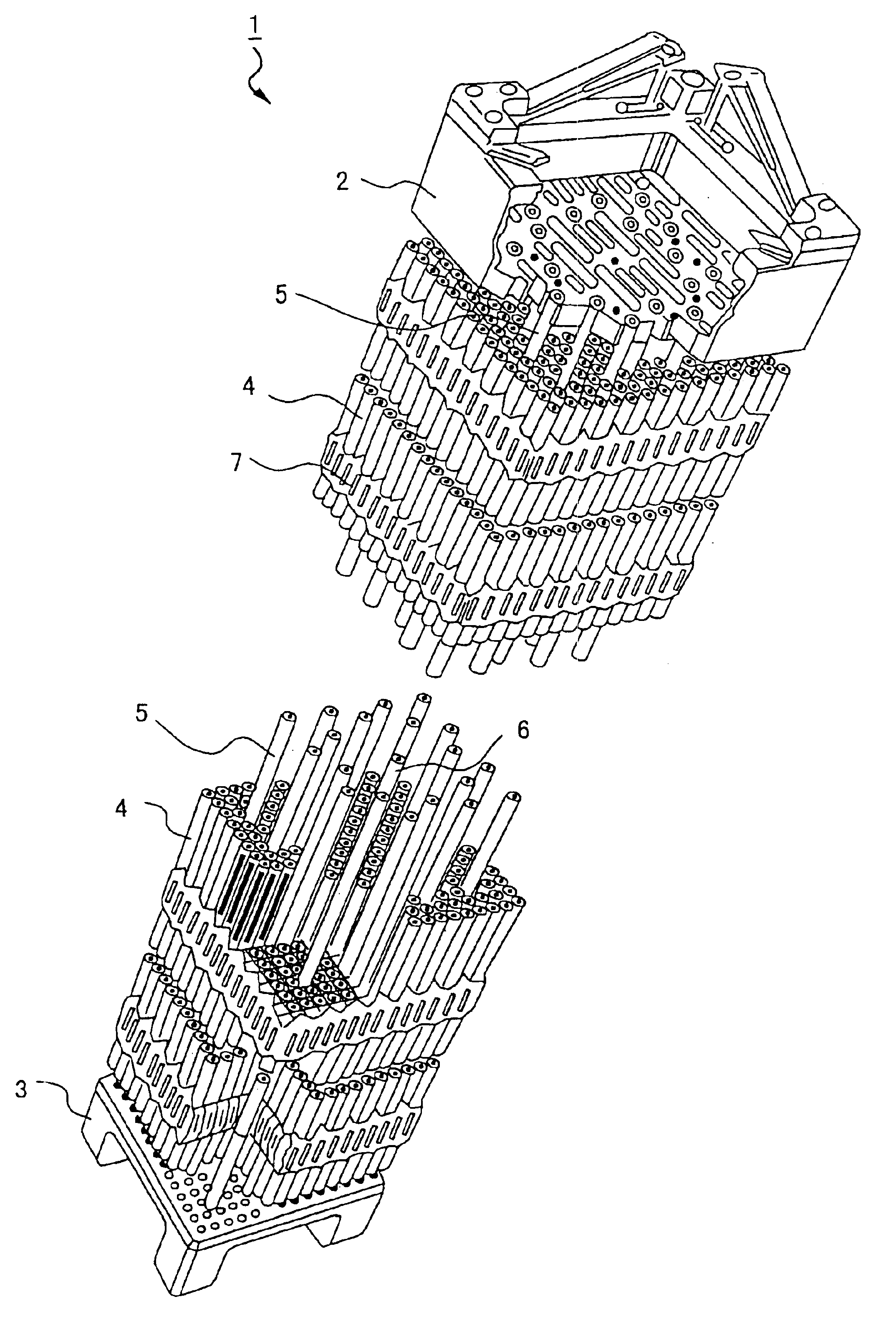
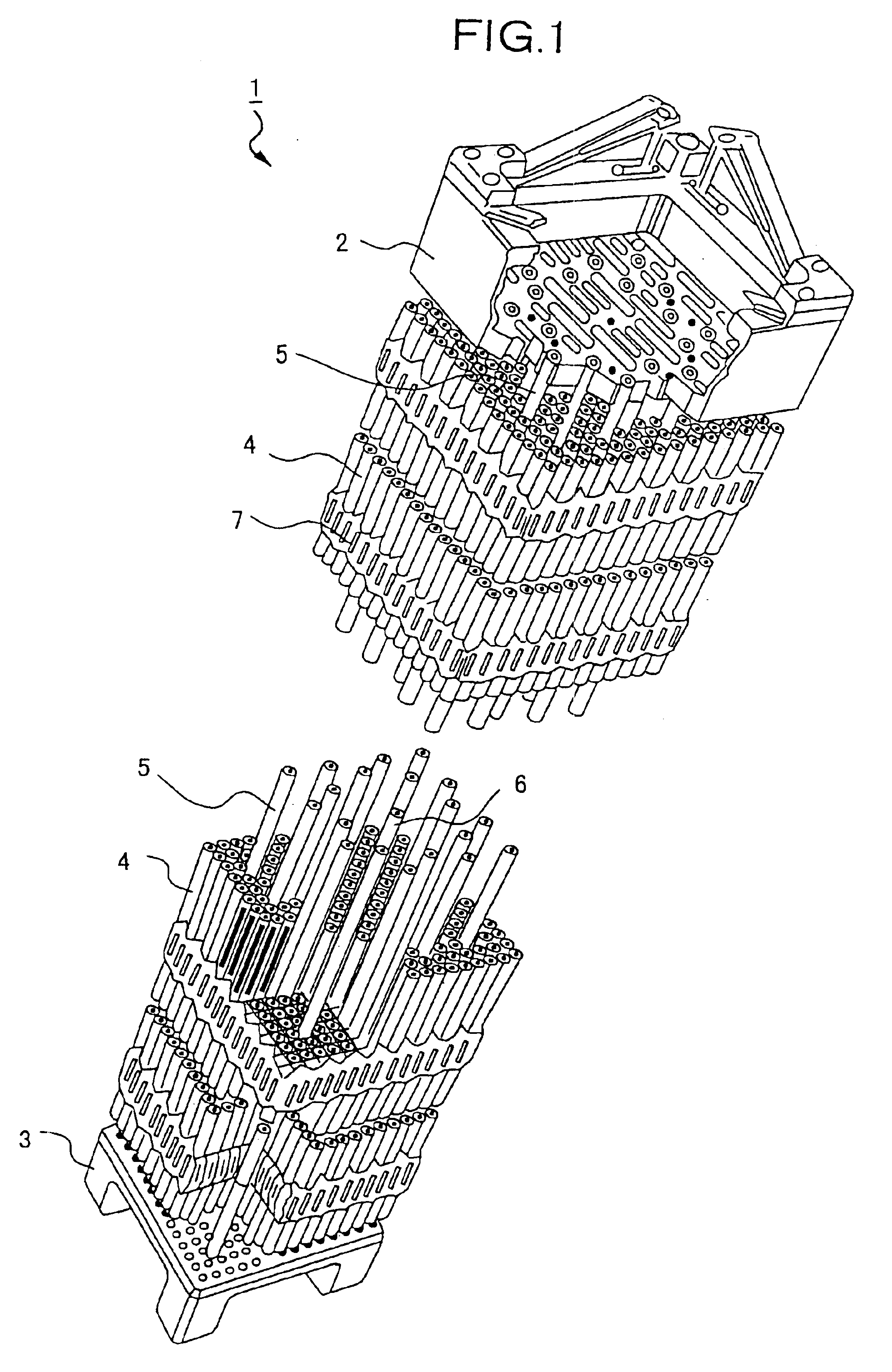
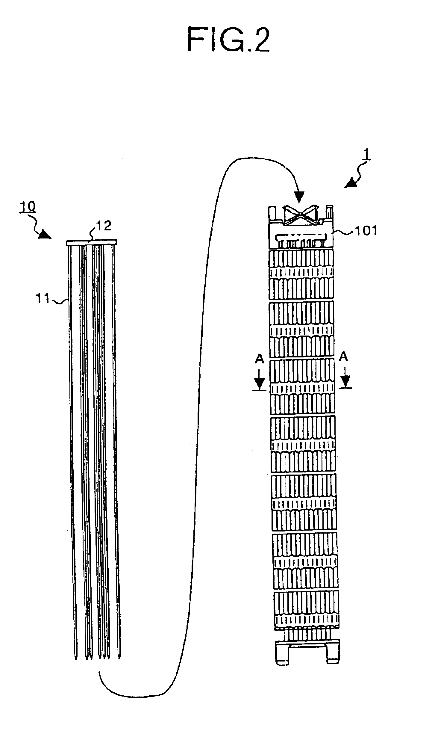
[0066] since the absorbing rods 11 having a neutron absorbing capability are inserted into the control rod guide pipes 5 and measuring pipes 6 of spent fuel assemblies, the neutrons can be absorbed by effectively utilizing the space in the control rod guide pipes 5 and measuring pipes 6, and emission of neutrons from the inside of the spent fuel assemblies can be reduced, and therefore the spacing distance for subcriticality between spent fuel assemblies can be shortened. Alternatively, by using the absorbing rod block 10 bonding a plurality of absorbing rods 11 by end plates 12, the absorbing rods 11 can be inserted in a batch form into the control rod guide pipes 5 and measuring pipes 6, so that the working efficiency is enhanced.

[0067]A second embodiment is explained below. The second embodiment relates to a cask for accommodating the spent fuel assemblies in which absorbing rods 11 of the first embodiment are inserted, which eliminates the cooling water passage provided in the p...

second embodiment

[0072]In the second embodiment, the cell 55 is composed by combining the plates 50 in lattice form. However, the cell may be formed with square pipes.

[0073]Further, when accommodating the spent fuel assemblies in the first embodiment, the thickness of the plates for composing the basket of the cask can be reduced corresponding to the neutron absorbing capability of the absorbing rods inserted in the spent fuel assemblies, so that the number of spent fuel assemblies accommodated in the cask can be increased. Further, it is not necessary to install the cooling water passage, which is the feature of the cask for PWR, in the plates or square pipes, and plates or square pipes of simple structure as in the plates or square pipes for BWR can be sued.

[0074]A third embodiment is explained below. In the first embodiment, by using the absorbing rod block 10 composed of a plurality of absorbing rods 11, the plurality of absorbing rods 11 are inserted in batch to enhance the working efficiency. ...

third embodiment

[0075]FIG. 7 shows the structure of the inserting apparatus according to the This inserting apparatus comprises an upper end plate 61 coupling the absorbing rod 11, a lower end plate 62 for guiding the absorbing rod 11, and a suspender 64 for moving the upper end plate 61.

[0076]The upper end plate 61 corresponds to the absorbing rod block 10. The upper end plate 61 and lower end plate 62 are suspended by the suspender 63. FIG. 8 is a sectional view taken along line B—B of the lower end plate 62. The lower end plate 62 has a guide hole 77 for guiding the absorbing rod 11. The guide hole 77 is provided corresponding to the position of the control rod guide pipe 5 and measuring pipe 6. When the upper end plate 61 and lower end plate 62 are suspended by the suspender 63, when stopping still or in the initial state, the leading end of the absorbing rod 11 must be at least inserted into the guide hole 77. The width of the upper end plate 61 and lower end plate 62 in the horizontal direct...


PUM


Abstract

The absorbing rods have a nearly the same shape as the shape of columnar control rods for PWR used in reactivity control of core in a reactor. The absorbing rods can shield neutrons, and are inserted in control rod guide pipes and measuring pipes in fuel assemblies.

Description

FIELD OF THE INVENTION[0001]The present invention relates to an absorbing rod having a neutron absorbing capability for being inserted into a control rod guide pipe of spent fuel assemblies, an inserting apparatus for inserting the absorbing rod into the control rod guide pipe, a cask for containing, conveying and storing the spent fuel assemblies, and a conveying and storing method of spent fuel assemblies.BACKGROUND OF THE INVENTION[0002]Fuel assemblies consumed and no longer usable in a terminal stage of fuel cycle are called spent fuels. Spent fuels contain fission products and other highly radioactive substances, and must be cooled thermally, and hence they are cooled for a specific period in a cooling pit at a nuclear power plant. Then they are transferred into a shielding container called cask, and conveyed and stored at reprocessing plant or storage facility by means of truck or ship. When transferring the spent fuel assemblies into the cask, a holding element having a latti...

Claims


Application Information

Patent Timeline
Patent Type & Authority Patents(United States)
IPC IPC(8): G21C19/00G21C19/40G21F5/008G21C19/06G21F5/06G21F5/012
CPCG21C19/40G21F5/008Y10S376/902G21Y2004/30G21Y2002/60Y02E30/30G21F5/06
Inventor SAKASHITA, KIICHIROITOH, TOMOHIROOHSONO, KATSUNARIHODE, SUGURU
Owner MITSUBISHI HEAVY IND LTD
Why Eureka
Try Eureka