Cooling-air cooler for a gas-turbine plant and use of such a cooling-air cooler

a technology of cooling air cooler and gas turbine plant, which is applied in the direction of machines/engines, combustion air/fuel air treatment, light and heating apparatus, etc., can solve the problems of requiring considerable control input, affecting the cooling effect of cooling air, and droppings having harmful effects during the cooling of thermally high-loaded parts, etc., to achieve the effect of small demands on the control of the sprayed water quantity

Inactive Publication Date: 2005-05-17
ALSTOM TECH LTD
View PDF20 Cites 39 Cited by
  • Summary
  • Abstract
  • Description
  • Claims
  • Application Information

AI Technical Summary

Benefits of technology

[0008]The object of the invention is therefore to provide a cooling-air cooler for gas-turbine plants having alternative cooling by spraying in water and / or steam generation, which cooling-air cooler does not have the disadvantages of known cooling-air coolers and in particular imposes considerably smaller demands on the control of the sprayed water quantity.
[0009]The essence of the invention is to separate excess water not evaporated by the cooling air by a water separator arranged on the air side. In this way, with at the same time improved cooling, a greater quantity of water can be sprayed in without damage occurring in the parts of the gas-turbine plant which are to be cooled. In this way, a protective function is built into the plant.
[0010]A preferred embodiment of the cooler according to the invention is characterized in that the first means are arranged directly downstream of the cooling-air inlet, in that the water separator is arranged directly upstream of the cooling-air outlet, and in that the second means are arranged between the first means and the water separator. As a result, a maximum flow path is achieved for the cooling air, and the latter can evaporate the sprayed water on this flow path while cooling down.

Problems solved by technology

The direct spraying of water into the cooling air flowing through the cooling-air cooler is not without problems: if too much water is sprayed in, the cooling air will possibly contain water droplets when leaving the cooling-air cooler, and these water droplets may have a harmful effect during the cooling of the thermally highly loaded parts of the gas-turbine plant, for example due to erosion.
If not enough water is sprayed in, the requisite cooling of the cooling air may possibly not be achieved.
This requires considerable control input.

Method used


Image

  • Cooling-air cooler for a gas-turbine plant and use of such a cooling-air cooler
  • Cooling-air cooler for a gas-turbine plant and use of such a cooling-air cooler
  • Cooling-air cooler for a gas-turbine plant and use of such a cooling-air cooler

Examples


Embodiment Construction

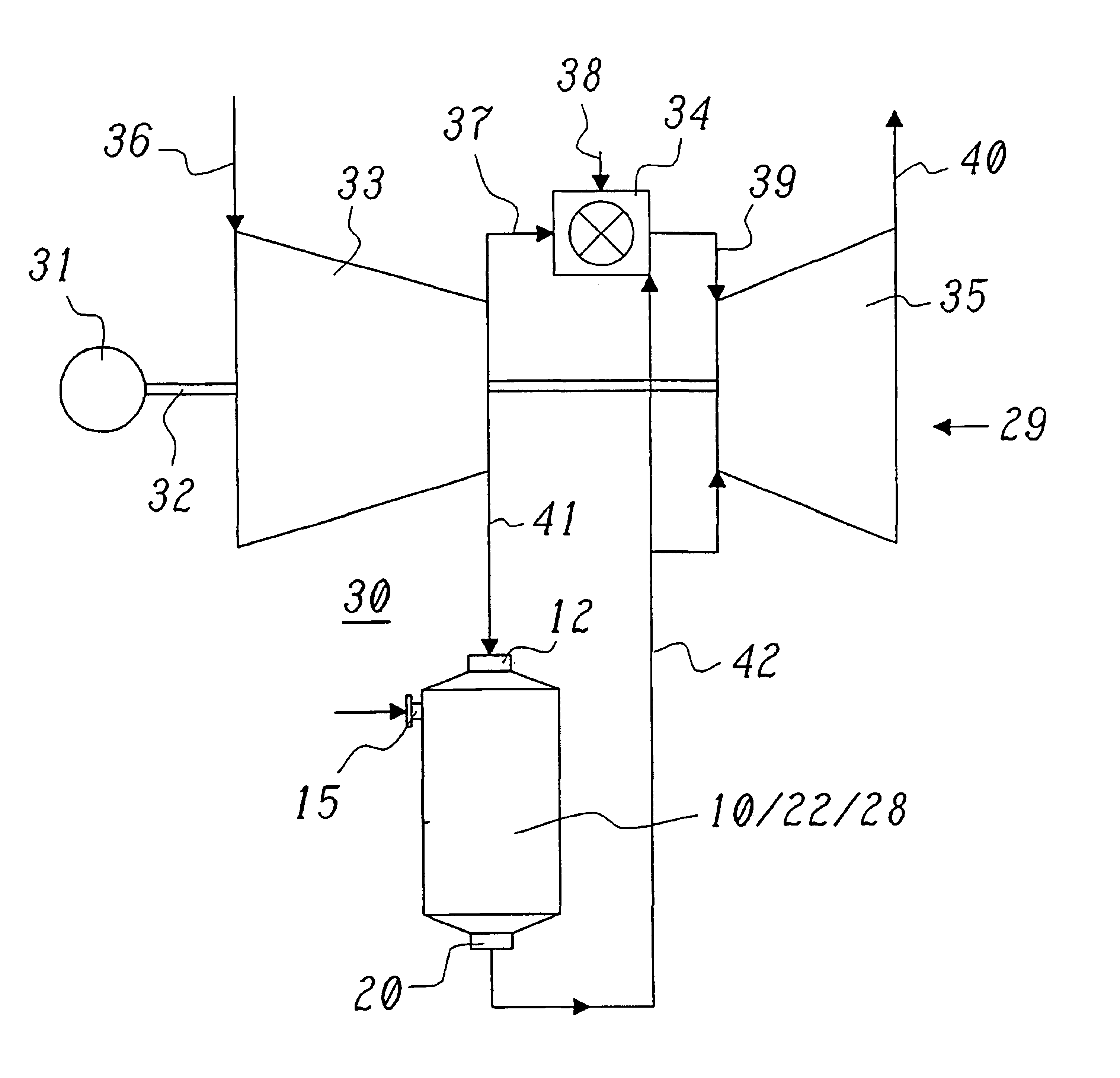
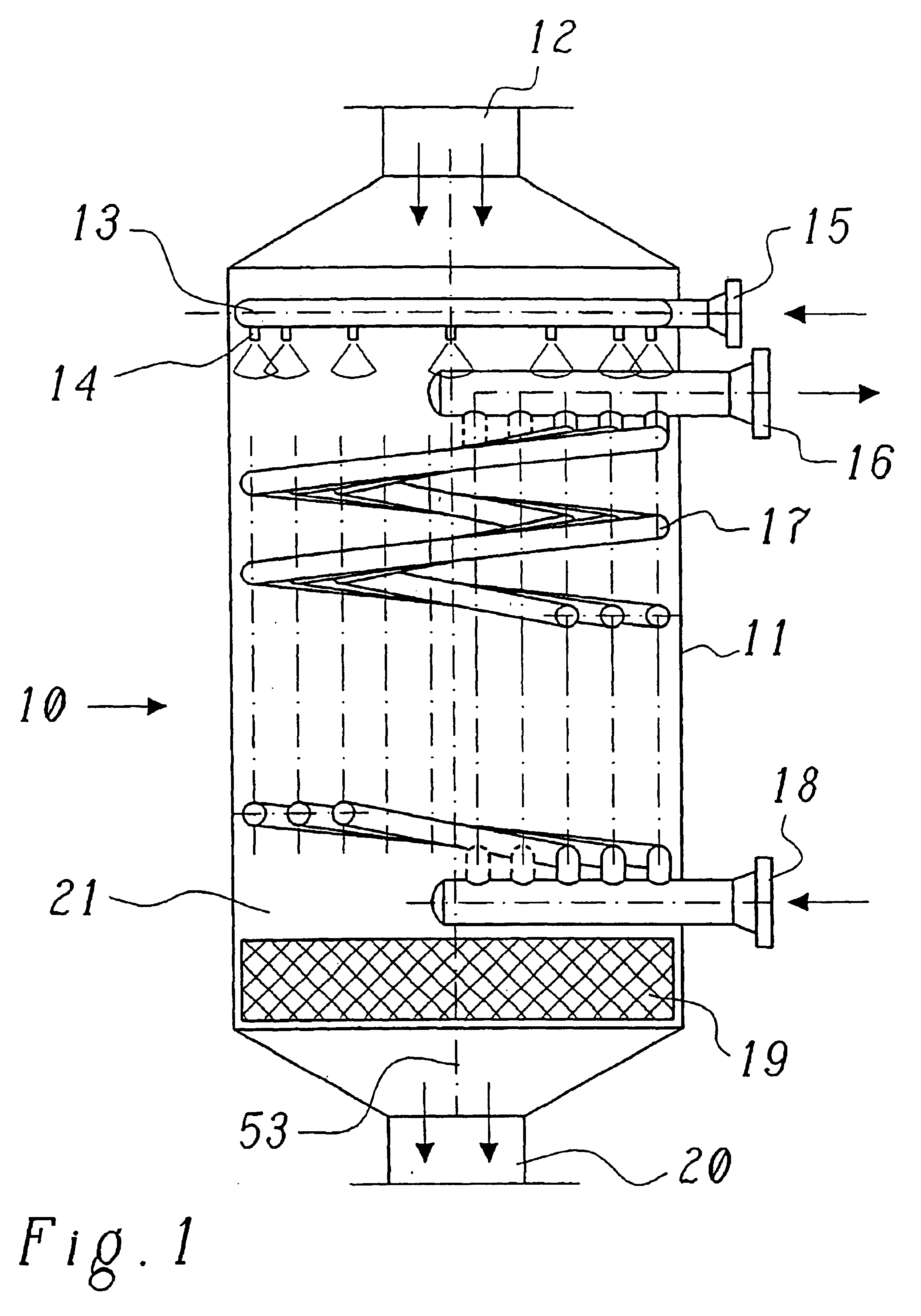
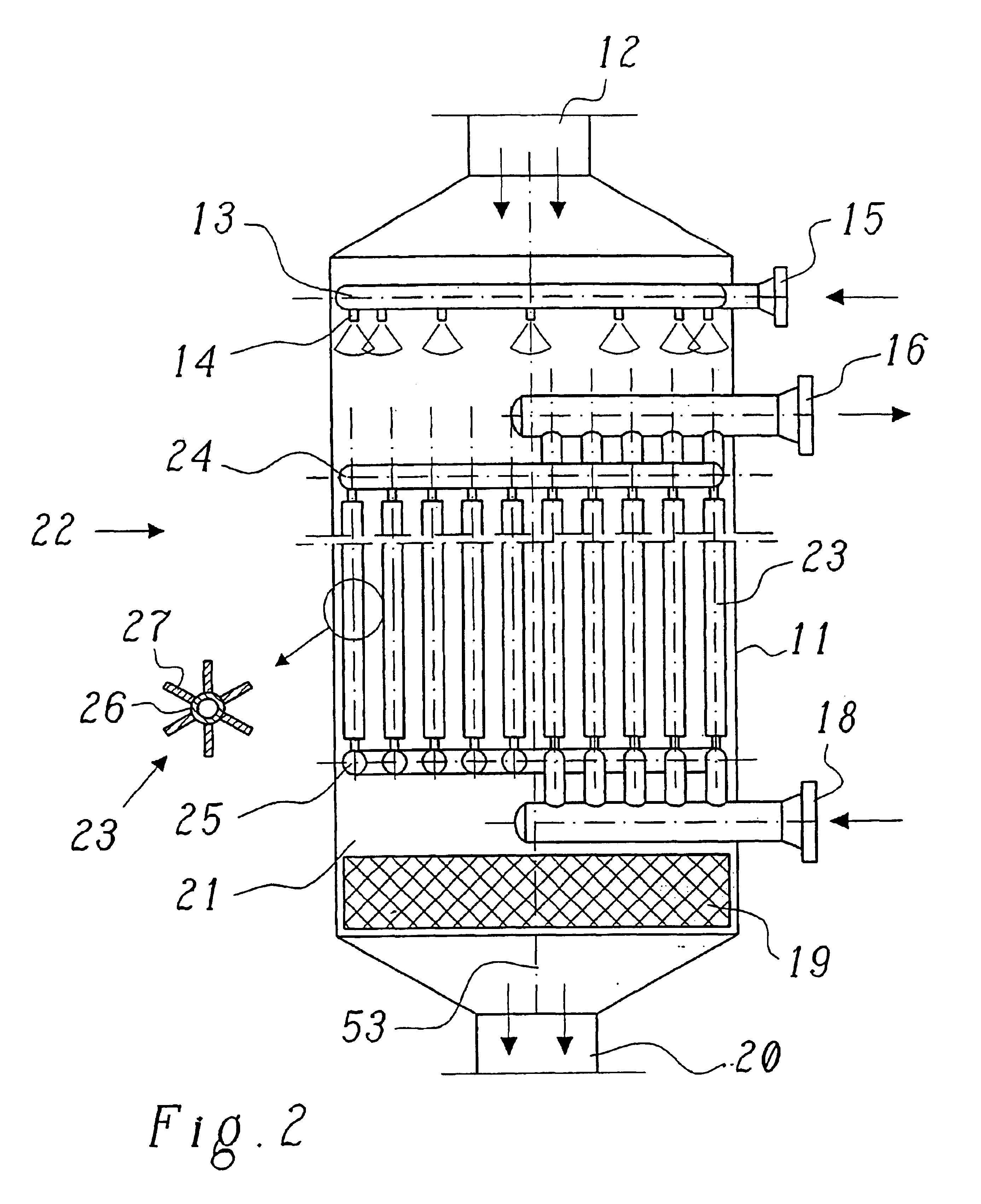
[0028]A cooling-air cooler in a first exemplary embodiment is shown in FIG. 1 in a simplified longitudinal section. The cooling-air cooler 10 comprises a preferably cylindrical pressure vessel 11 which—in an upright position—has a cooling-air inlet 12 at the top and a cooling-air outlet 20 at the bottom. During operation, the cooling air to be cooled flows from top to bottom (in the direction of the double arrows) through the interior space 21 of the pressure vessel 11.

[0029]The cooling of the cooling air in the cooling-air cooler 10 may now be effected in two different ways: In one case, water is sprayed into the cooling-air flow, and this water evaporates in the hot cooling-air flow and thus extracts heat from the cooling air. Provided for this purpose in the pressure vessel 11 downstream of the cooling-air inlet is a water-spraying device which comprises a ring line 13 having a plurality of attached injection nozzles 14 directed downward. The water to be sprayed is fed to the rin...


PUM


Abstract

In a cooling-air cooler for a gas-turbine plant of a power plant, in which cooling-air cooler first means for spraying water into the cooling-air flow and second means for generating steam are arranged in a pressure vessel, through which the cooling air flows, between a cooling-air inlet and a cooling-air outlet in the cooling-air flow, simplified operation is achieved in that a water separator is provided on the cooling-air side in the direction of flow downstream of the first means.

Description

[0001]This application is a continuation of application Ser. No. 09 / 758,187, filed on Jan. 12, 2001 now abandoned.FIELD OF THE INVENTION[0002]The present invention relates to the field of power plant technology. It concerns a cooling-air cooler for a gas-turbine plant of a power plant. The invention also relates to the use of such a cooling-air cooler.BACKGROUND OF THE INVENTION[0003]Such a cooling-air cooler has been disclosed, for example, by European Patent Application EP-A1-0 773 349 of the applicant.[0004]In gas-turbine plants it is normal practice to branch off some of the combustion air drawn in and compressed by the compressor as cooling air, to cool it down in a downstream cooling-air cooler and to use it for cooling thermally loaded parts of the turbine and / or the combustion chamber. If the gas-turbine plant, taken on its own, works in an open gas cycle (simple cycle), that is, for example, in a gas-turbine power plant, or in combination with a steam cycle (combined cycle)...

Claims


Application Information

Patent Timeline
Patent Type & Authority Patents(United States)
IPC IPC(8): F01K21/00F01K23/10F01K21/04F02C7/143F02C7/12F28D7/16F28D7/00F28C3/08F28C3/00F28D7/02
CPCF01K21/047F01K23/106F02C7/1435F28C3/08F28D7/0091F28D7/024F28D7/16F28D7/0066Y02E20/16
Inventor FETESCU, MIRCEALIEBIG, ERHARD
Owner ALSTOM TECH LTD
Why Eureka
Try Eureka