Current collector having non-symmetric grid pattern converging at a common focal point

a current collector and grid pattern technology, applied in the field of chemical energy conversion to electrical energy, can solve the problems of reducing the internal resistance of the current collector, and achieve the effects of reducing the flow path of electrons, reducing the rdc, and reducing the number of cells

Inactive Publication Date: 2005-05-17
WILSON GREATBATCH LTD
View PDF24 Cites 20 Cited by
  • Summary
  • Abstract
  • Description
  • Claims
  • Application Information

AI Technical Summary

Benefits of technology

[0005]A characteristic of any electrochemical cell is its internal resistance (Rdc). It is well known that the design, shape and configuration of a current collector and its grid pattern affect Rdc. Placing an external load on an electrochemical cell causes a chemical reaction that produces a flow of electrons through the current collector to the associated external battery terminal. The basis of the present invention is to reduce Rdc by reducing the flow path of electrons. In other words, the distance electrons must travel between all points on the current collector and the cell terminal is reduced.
[0007]In that light, the internal resistance of the present current collector is reduced with respect to conventional designs by providing a more direct path to the connector tab. The improved grid structure has a fan-like configuration of radiating conductors so that every portion of the current collector is either along a straight, radiating path to the connector tab or, is relatively proximate a radiating conductor.

Problems solved by technology

This results in the current collector having reduced internal resistance in comparison to conventional current collector designs.

Method used


Image

  • Current collector having non-symmetric grid pattern converging at a common focal point
  • Current collector having non-symmetric grid pattern converging at a common focal point
  • Current collector having non-symmetric grid pattern converging at a common focal point

Examples


Embodiment Construction

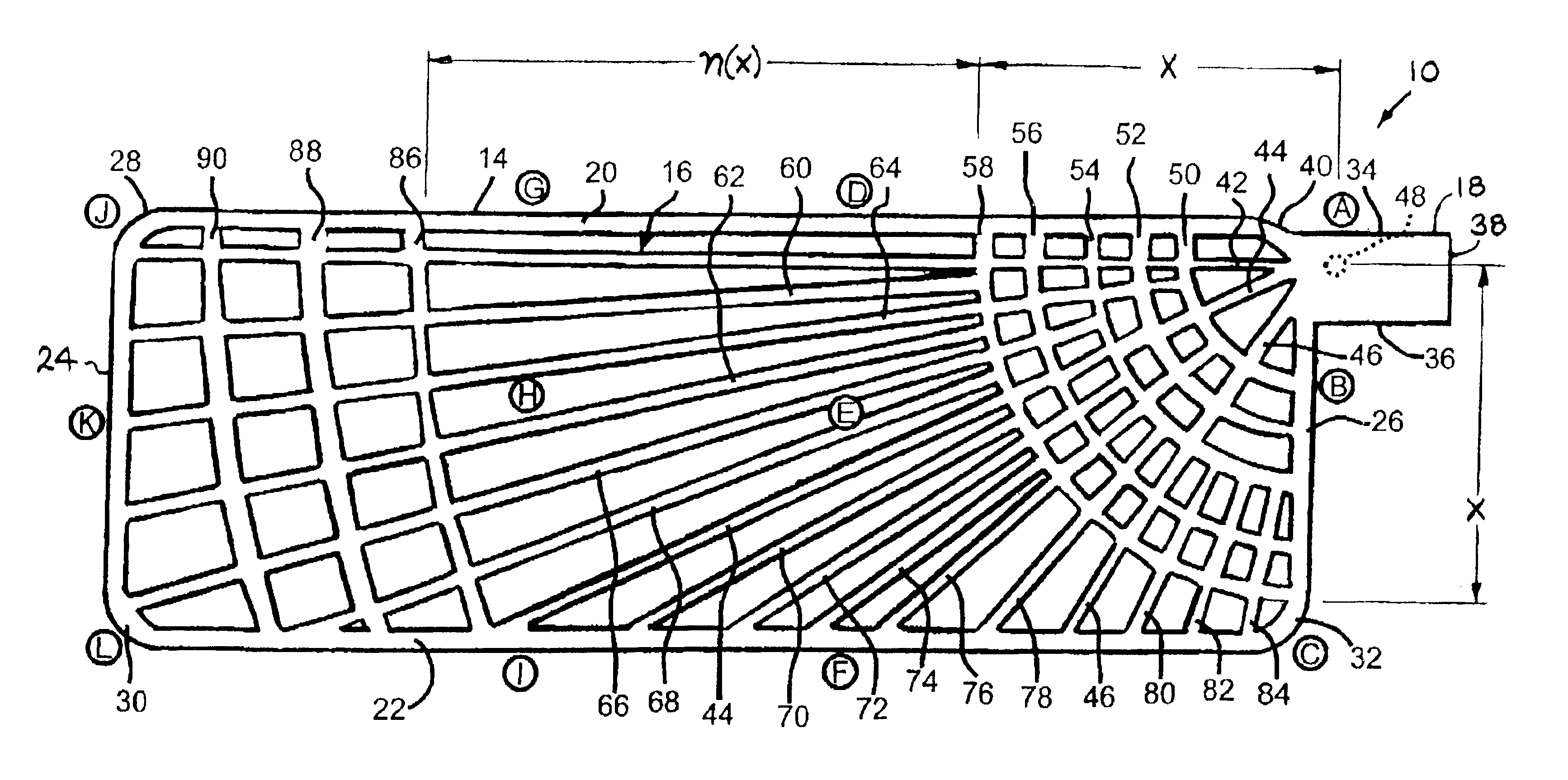
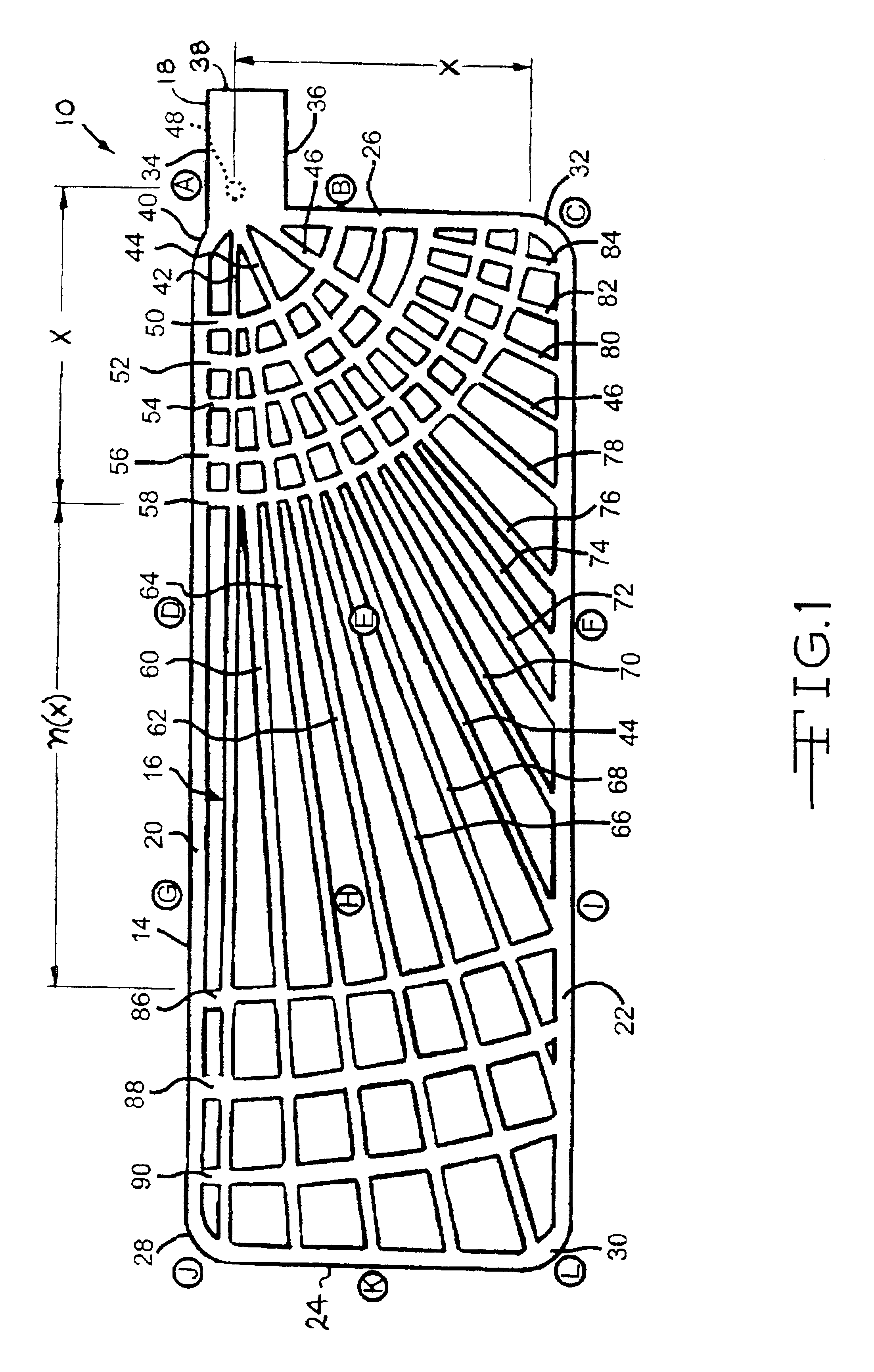
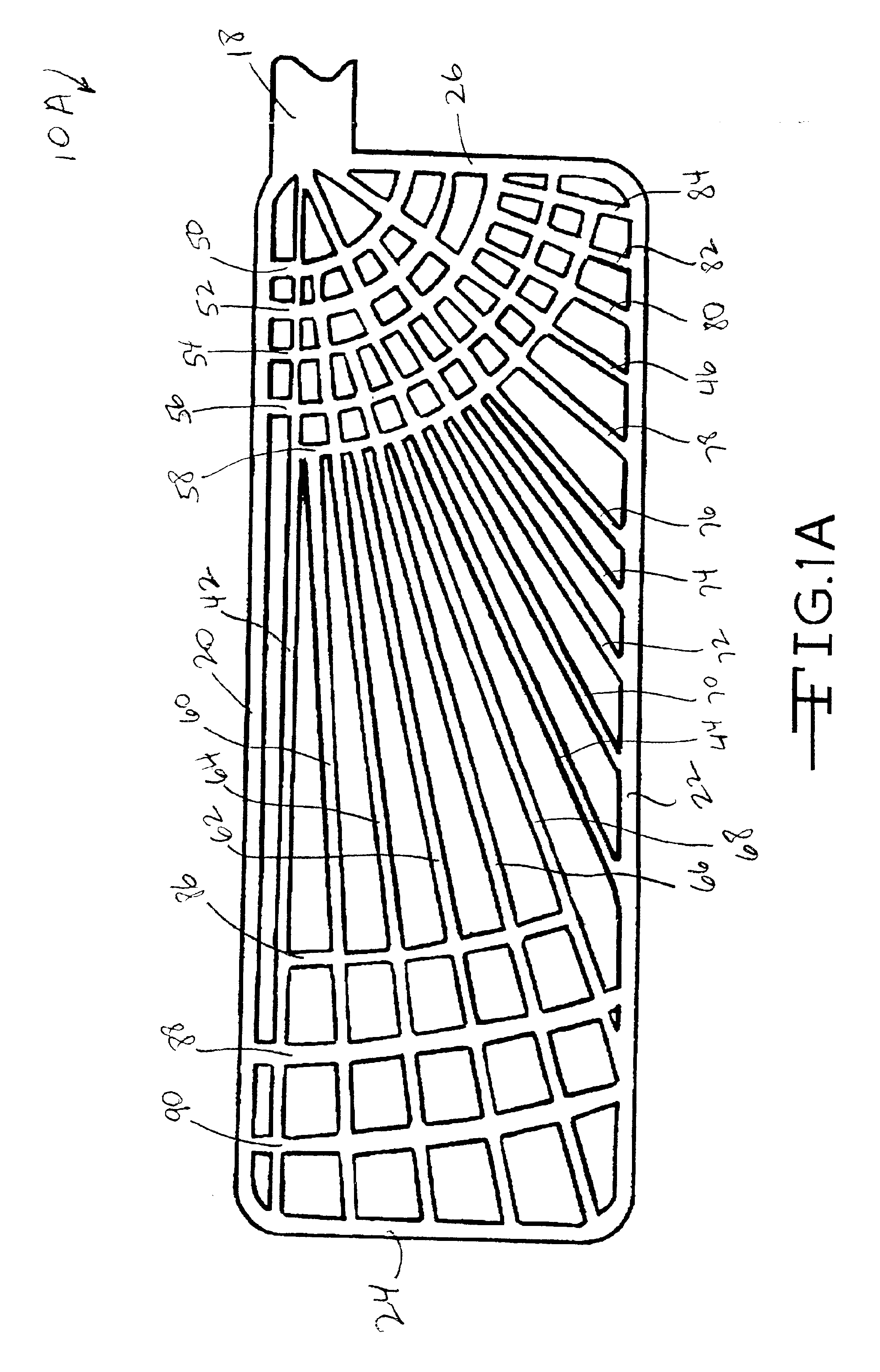
[0016]Referring now to the drawings, FIG. 1 shows an enlarged view of one embodiment of a current collector 10 according to the present invention while FIG. 2 shows another embodiment of the present current collector 12 having a double wing configuration. FIG. 3 is of an exemplary electrochemical cell 100 of a multi-plate configuration comprising one of the present current collectors. Whether the current collector of the cell 100 is of the single wing configuration 10 or of the double wing type 12 is not necessarily important.

[0017]As shown in the enlarged view of FIG. 1, the current collector 10 generally comprises wire or bar-shaped conductor strands in the shape of a frame 14 surrounding a grid 16 and supporting a tab 18. The conductors and tab are of a conductive material such as nickel, aluminum, copper, stainless steel, tantalum, cobalt and titanium, and alloys thereof. As shown in this figure, the frame 14 has spaced apart upper and lower strands 20 and 22 extending to and me...


PUM

PropertyMeasurementUnit
currentaaaaaaaaaa
perimeteraaaaaaaaaa
distanceaaaaaaaaaa

Abstract

The present invention relates to a current collector for an electrochemical cell. The current collector has a unique grid structure comprised of a frame supporting a plurality of radial strands as conductors radiating outwardly from a focal point on a connector tab. The frame and radial conductors are maintained in a fan-like orientation with respect to each other by two groups of concentric conductor strands, one located adjacent to the tab, the other spaced a substantial distance therefrom. The radiating conductors provide a more direct path to the connector tab for electron flow. This results in the current collector having reduced internal resistance in comparison to conventional current collector designs.

Description

CROSS REFERENCE TO RELATED APPLICATION[0001]This application claims priority from provisional application Ser. No. 60 / 269,131, filed Feb. 15, 2001.FIELD OF THE INVENTION[0002]The present invention relates to the conversion of chemical energy to electrical energy. More particularly, the present invention relates to a current collector having lower internal resistance (Rdc) in comparison to current collectors of a conventional design. The present current collector is useful in electrochemical cells of both aqueous and non-aqueous chemistries.BACKGROUND OF THE INVENTION[0003]Present electrochemical cell designs utilize two primary construction methods. Either the internal electrodes are spirally wound or, they are assembled in a multiple plate configuration. In either case, each of the positive and negative electrodes is comprised of a current collector and active chemical constituents contacted thereto. The current collector can either be the casing housing the cell or, a conductive f...

Claims


Application Information

Patent Timeline
Patent Type & Authority Patents(United States)
IPC IPC(8): H01M4/72H01M4/66H01M10/04
CPCH01M4/72H01M10/045H01M10/0413H01M4/661Y10T29/49108Y10T29/10Y02E60/10Y02P70/50
Inventor PROBST, JOSEPH M.
Owner WILSON GREATBATCH LTD
Why Eureka
Try Eureka