
Apparatus for aerating a particulate material

Inactive Publication Date: 2005-05-17
CH2M HILL
View PDF21 Cites 9 Cited by
  • Summary
  • Abstract
  • Description
  • Claims
  • Application Information

AI Technical Summary

Benefits of technology

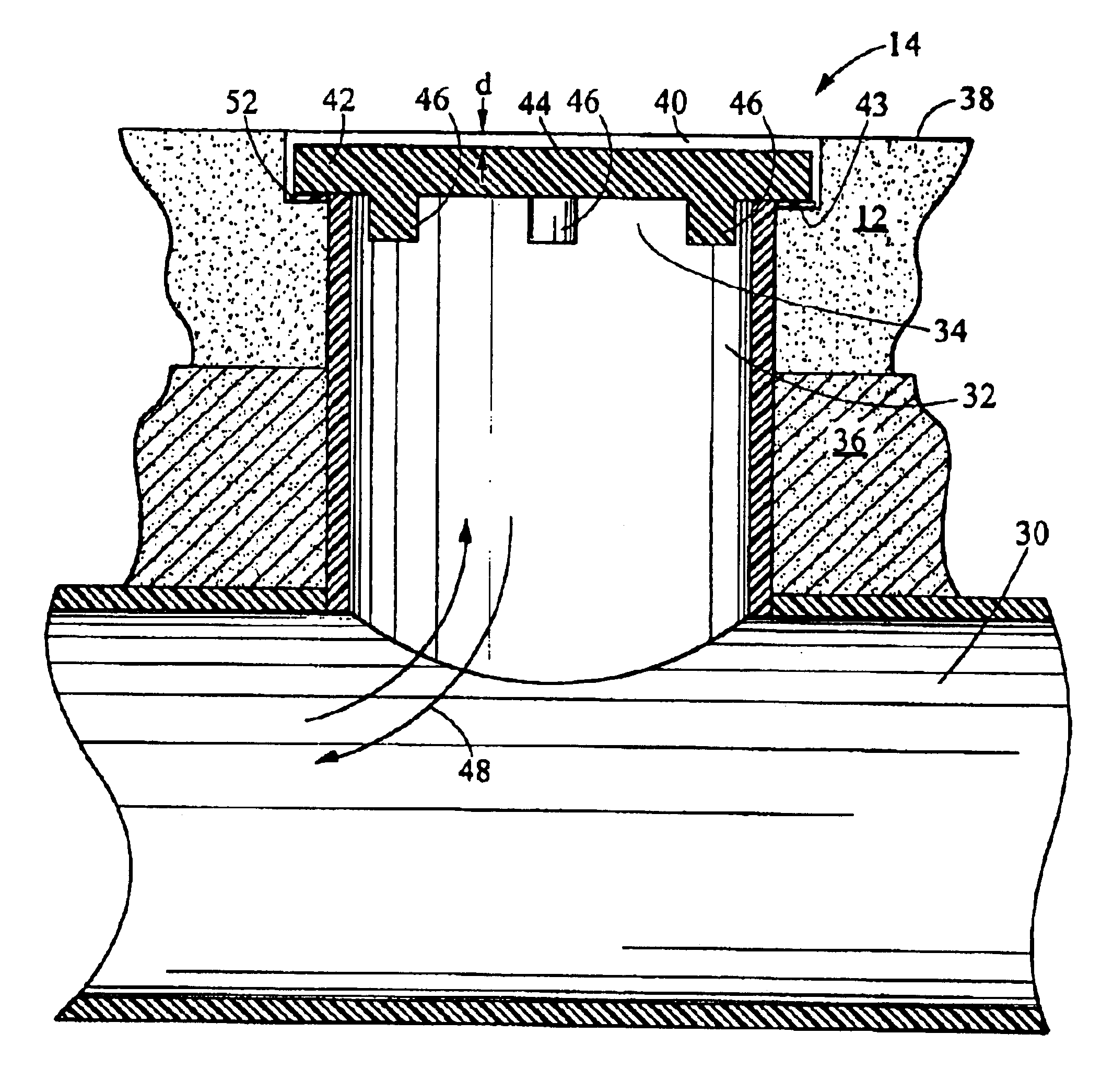
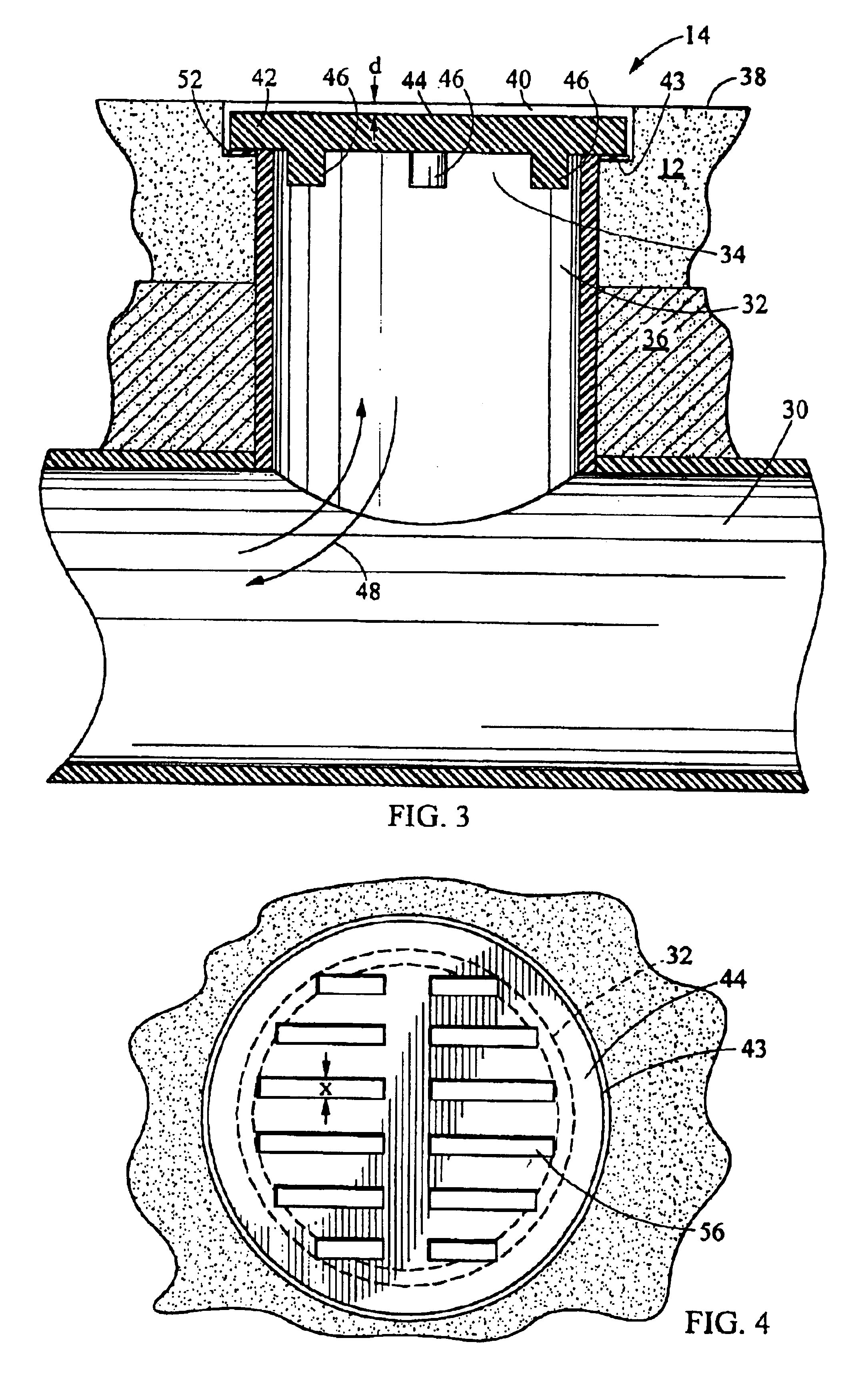
[0012]The apparatus for aerating particulate material in accordance with the present invention eliminates the recess over the air grate of the Cedar Grove system and, therefore, enables a more uniform air flow than obtainable using the Cedar Grove system. The system also eliminates the expense and difficulty associated with using tees in the recesses necessitated by the Cedar Grove system in order to maintain uniform air flow. The grate openings are sized to allow material to fall through the grate rather than obstructing the grate. This material may then be removed by vacuuming the conduits or applying a back pressure to the conduits. The system of the present invention provides grates which are securely positioned over the delivery conduits, thus eliminating displacement of the grates which could allow uncontrolled entry of material into the delivery conduits, producing blockage and uneven air flow. The grates are also durable enough to sustain the load of equipment used in moving and treating the compost.

Problems solved by technology

In practice, debris gets packed into the recess overlying the grates and significantly inhibits the flow of air through the grates, thus diminishing efficient composting.
The cost of the tees as well as the time and effort required to place and replace the tees in the recess increases the cost of this composting system.
Another problem with the system of Finn involves accidental displacement of the grates.
This allows a large volume of material to enter the air channels and disrupts a uniform air flow.
Also, the small slits described in Finn (0.05-0.063 inch at the surface) cannot accommodate high moisture conditions that cause hydraulic swelling of smaller organic matter particles.
In addition, the linear system of Finn is subject to non-uniform air flow from one end of an air channel to another in the event of displacement of a grate or varying back pressures caused by non-uniform distribution of composting material over the grates.

Method used


Image

  • Apparatus for aerating a particulate material
  • Apparatus for aerating a particulate material
  • Apparatus for aerating a particulate material

Examples


Embodiment Construction

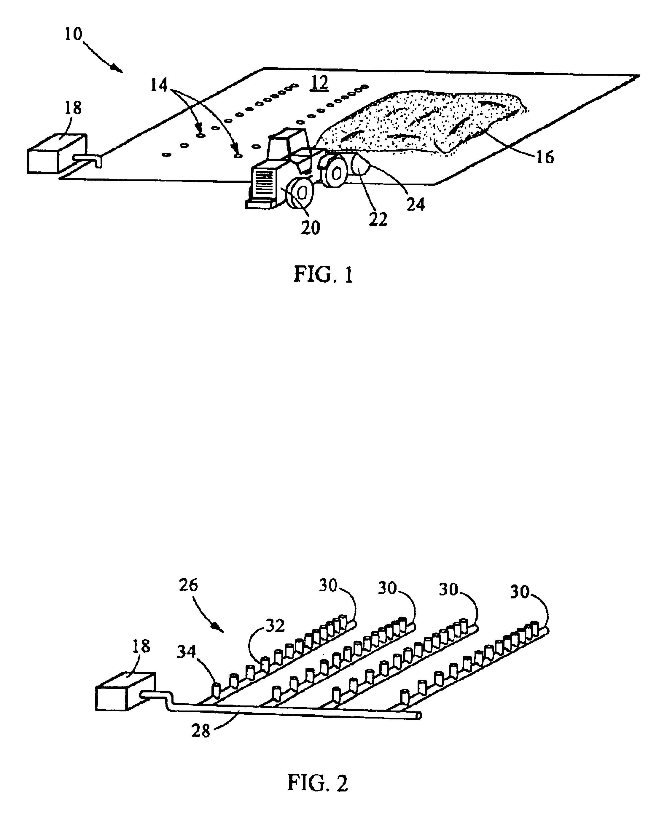
[0017]An apparatus for aerating particulate material 10 of the present invention is illustrated in FIG. 1. The apparatus consists of a pavement slab 12 having a number of rows of vent holes 14 for aerating particulate material 16 deployed on the pavement slab 12. A pressurized air source 18 is in operative association with an air conveyance system 26 which will be discussed below with respect to FIG. 2. The pressurized air source 18 is configured either to provide air under positive pressure or negative pressure (i.e., to create a vacuum at the vent holes 14). The pavement slab 12 and the vent holes 14 are intended to bear material moving equipment 20. The material moving equipment 20 may include a plow or front end loader 22 or other implement having a linear edge 24 abutting a planar bearing surface 38 (shown in FIG. 3) of the pavement slab 12 to allow for manipulation and loading of the particulate material 16.

[0018]In a preferred embodiment, the particulate material 16 consists ...


PUM


Abstract

An apparatus for forcing airflow through (i.e., aerating) a particulate material consists of a planar bearing surface and a ventilation conduit underlying the planar bearing surface. A plurality of delivery conduits extend between the ventilation conduit and the planar bearing surface with a mouth of the delivery conduits being near the planar bearing surface. A grate, defining a plurality of openings, covers the mouth of each delivery conduit. Each grate has a top surface substantially parallel to the planar bearing surface and positioned at or no more than a select distance below the planar bearing surface. This select distance is close enough to the planar bearing surface to prevent the accumulation of particulate material over the grate as the particulate material is scraped from the planar bearing surface with an implement having a linear edge abutting the planar bearing surface.

Description

BACKGROUND OF THE INVENTION[0001]1. Technical Field[0002]The present invention is directed toward aeration of particulate material, and more particularly toward an apparatus for aerating particulate material such as compost.[0003]2. Background Art[0004]Increasing waste production and decreasing capacity for waste disposal has led to exploration of alternatives for conventional landfilling of waste. The ability to compost organic waste to reduce the volume of waste and produce a usable byproduct has led to expansion of the composting industry.[0005]One known method and apparatus for composting is disclosed in Allen, U.S. Pat. No. 6,099,613 (the “Cedar Grove patent”), the contents of which are incorporated herein in their entirety. The Cedar Grove patent is directed to a composting system and apparatus using pavement as a bearing surface for piles of particulate composting material. A plurality of ventilation conduits underlie the pavement surface and a plurality of delivery conduits ...

Claims


Application Information

Patent Timeline
IPC IPC(8): C05F17/02
CPCC05F17/027Y02P20/145C05F17/979Y02W30/40
Inventor ALLEN, JAN
Owner CH2M HILL
Learn More