High efficiency passive piezo energy harvesting apparatus

a piezoelectric device and high efficiency technology, applied in the field of piezoelectric device energy harvesting, can solve the problems of wasting energy generated by piezoelectric devices, each switch and its controlling circuitry dispersing a portion, etc., to reduce the power loss of the circuit, maximize the energy discharged, and reduce the power consumption of the diode

Inactive Publication Date: 2005-05-17
THE BOEING CO
View PDF19 Cites 67 Cited by
  • Summary
  • Abstract
  • Description
  • Claims
  • Application Information

AI Technical Summary

Benefits of technology

[0009]In a preferred embodiment of the present invention, a voltage regulator is included adjacent to the power storage element. The diodes of the present invention are preferably nano-second time response diodes to follow the operating frequency of the piezoelectric device. The diodes of the present invention provide a passive switching operation, advantageously using the switching capability and low power consumption of diodes to reduce the power loss of the circuit and maximize the energy discharged from the piezoelectric device and stored in the power storage element.

Problems solved by technology

The disadvantage of discharging a piezoelectric device directly to a capacitor is that the energy generated by the piezoelectric device is not fully utilized.
The disadvantage of using switches is that each switch and its controlling circuitry dissipates a portion of the already low charge of the piezoelectric device before it reaches the energy storage element.

Method used


Image

  • High efficiency passive piezo energy harvesting apparatus
  • High efficiency passive piezo energy harvesting apparatus
  • High efficiency passive piezo energy harvesting apparatus

Examples


Embodiment Construction

[0018]The following description of the preferred embodiment(s) is merely exemplary in nature and is in no way intended to limit the invention, its application, or uses.

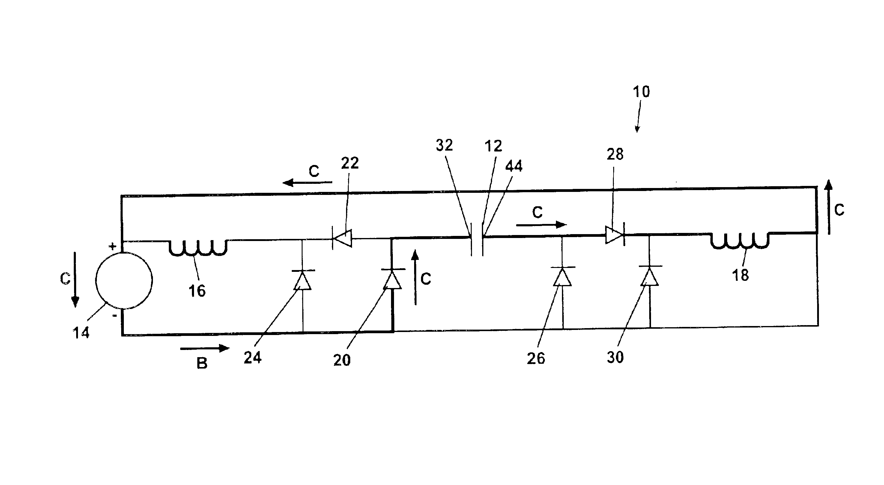
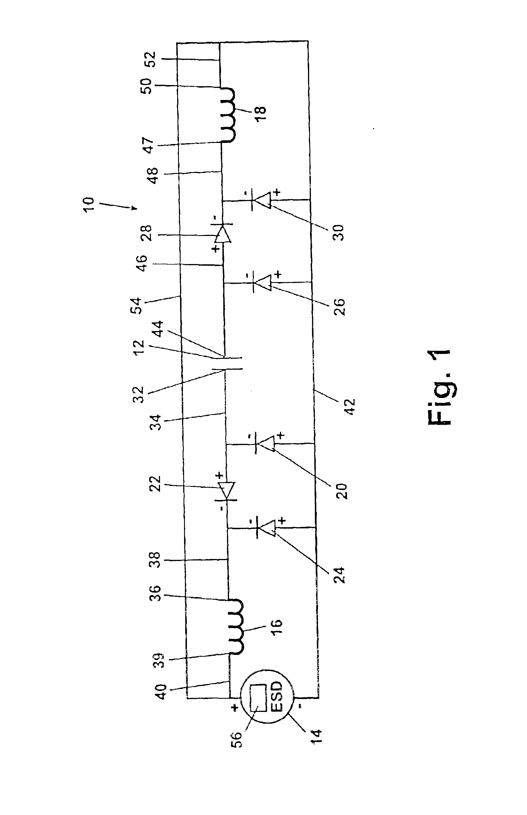
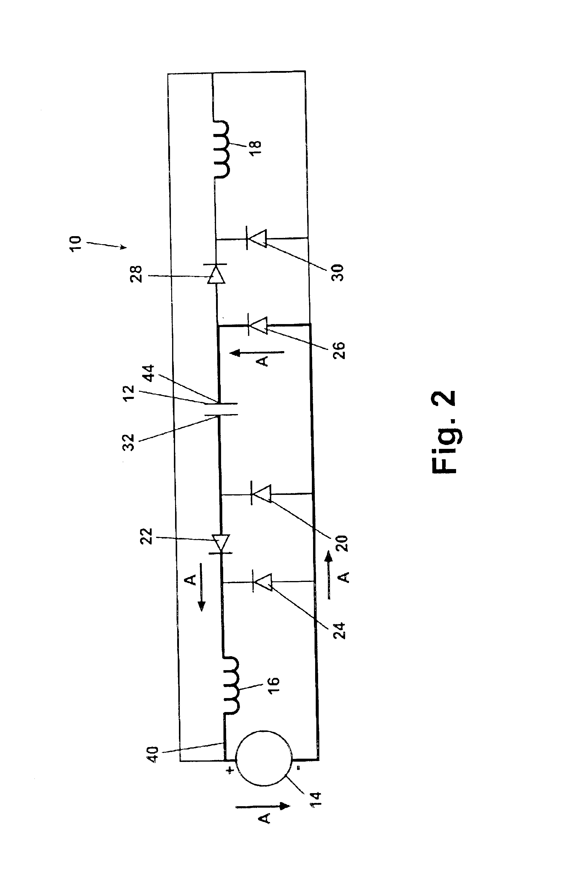
[0019]Referring to FIG. 1, a passive circuit 10 in accordance with a preferred embodiment of the present invention is shown. The circuit 10 is used for discharging the energy stored in a piezoelectric device 12 to an energy storage element 14. The passive circuit 10 includes a first inductor 16 and a second inductor 18. The passive circuit 10 also includes a plurality of diodes, and in the embodiment shown six diodes: a first diode 20, a second diode 22, a third diode 24, a fourth diode 26, a fifth diode 28 and a sixth diode 30.

[0020]The diodes are disposed in the passive circuit 10 such that a cathode terminal of the first diode 20 is connected to a first terminal 32 of device 12 via a connector 34. An anode terminal of the second diode 22 is also connected to the connector 34 and thereby to the first terminal 32. Th...


PUM

PropertyMeasurementUnit
frequenciesaaaaaaaaaa
energyaaaaaaaaaa
currentaaaaaaaaaa

Abstract

A circuit passively discharges energy from a piezoelectric device and stores the energy in a power storage element. The circuit has two parallel flow paths each including a diode set and an inductor electrically connected to opposite sides of a piezoelectric device. A power storage element is connected to both inductors. The diode sets are alternately forward biased, and energy from the piezoelectric device discharges through the inductor(s). A portion of the energy is stored in the inductor(s) and the remaining portion is stored in the power storage element. The benefits achieved include passive switching between the parallel circuit paths through diodes in place of traditional switches, and the additional energy stored by the inductors which is also transferred to the power storage element. Passive switching conserves additional energy.

Description

FIELD OF THE INVENTION[0001]The present invention relates in general to piezo device energy harvesting and more specifically to a method and apparatus to discharge and store electrical energy from piezoelectric devices.BACKGROUND OF THE INVENTION[0002]Piezoelectric devices are known which can be used as a power source and are particularly useful for remote applications where other power sources such as batteries or generators are impractical. In common applications, the energy of the piezoelectric device is harvested and stored in an energy storage element. Piezoelectric devices internally produce energy as the device vibrates. The energy available from a piezoelectric device increases as the square of the voltage. The relationship is that the energy (E) stored in a device equals ½ CV2, C being the capacitance of the device and V being the voltage. Although the energy of the device increases as a squared function, the charge available goes up linearly.[0003]Common circuits to discha...

Claims


Application Information

Patent Timeline
Patent Type & Authority Patents(United States)
IPC IPC(8): H01L41/113H01L41/00H01L41/04H02N2/18
CPCH02N2/181
Inventor CLINGMAN, DAN J.
Owner THE BOEING CO
Why Eureka
Try Eureka