Method of regulating the supply voltage of a load and related voltage regulator

a technology of supply voltage and voltage regulator, which is applied in the direction of electric variable regulation, instruments, and apparatus without intermediate ac conversion, etc., can solve the problem of limiting the speed of current variation, regulators are relatively slow at regulating output voltage to its reference value, and no longer true, so as to improve the accuracy of known controllers

Inactive Publication Date: 2005-05-17
STMICROELECTRONICS SRL
View PDF10 Cites 203 Cited by
  • Summary
  • Abstract
  • Description
  • Claims
  • Application Information

AI Technical Summary

Benefits of technology

[0047]An object of the invention is to enhance the accuracy of known controllers. It has been found that disturbances on the signal VCOMP due to the magnetic field generated by the inductor, the offset of the comparator and the oscillations of the signal VCOMP do not produce any effect on the output voltage if the difference between the output voltage and the reference voltage is integrated. This happens because disturbances are eliminated if they manifest themselves as (equivalent) voltages superposed to the voltage VCOMP (that is if these voltages are introduced downstream of the integrator), independently from their mean value, because of the infinite DC gain of the integrator. Disturbances induced upstream of the integrator do not produce any output error because their mean value is zero.
[0052]The regulator of the invention reduces the effects on the regulated output voltage of disturbances that corrupts the error signal, because said circuit means comprise an integrator of the sum between the voltage signal and the difference, scaled by a certain quantity, between the output voltage and the reference voltage. The turn on or the turn off of the switch is commanded in function of the state of the logic signal according to whether a regulator with a constant turn on time or with a constant turn off time is implemented. In case of a constant turn on time (TON) control, the signal generated by the comparator forces the turning on while the turning off is forced by a timer of by a clock after a certain time TON from the turning on instant. In case of a constant turn off time (TOFF) control, the comparator forces the turning off while the turning on is forced by a timer or a clock a certain time after the turning off instant. If the comparator has hysteresis, it will determine both the turn on and turn off instants. In case a clock signal is used to determine the turn on and / or the turn off instants, the comparator should be input also with a “slope compensation” signal.

Problems solved by technology

Of course, during a load transient this is no longer true.
These regulators are relatively slow at regulating the output voltage to its reference value after a load variation has occurred, because they are never capable of reacting sufficiently fast to a very fast load transient.
There is in fact a limit to the speed (slew-rate limitation) of variation of the current that the output power stage may furnish to the electric parallel of the load and of the output capacitor.
It is easy to notice that in this way it is not possible to satisfy the condition ZOUT=ESR.
A problem that burdens known regulators, independently from the position in respect to the supply voltage source of the switches that drive the inductor, consists in that the comparator has an offset voltage that reduces the accuracy with which the output voltage is regulated.
Both expedients complicate remarkably the realization of the regulator.
Another type of inaccuracy of the known regulators is caused by the oscillations of signal VCOMP due to the oscillations of the current flowing in the inductor.

Method used


Image

  • Method of regulating the supply voltage of a load and related voltage regulator
  • Method of regulating the supply voltage of a load and related voltage regulator
  • Method of regulating the supply voltage of a load and related voltage regulator

Examples


Embodiment Construction

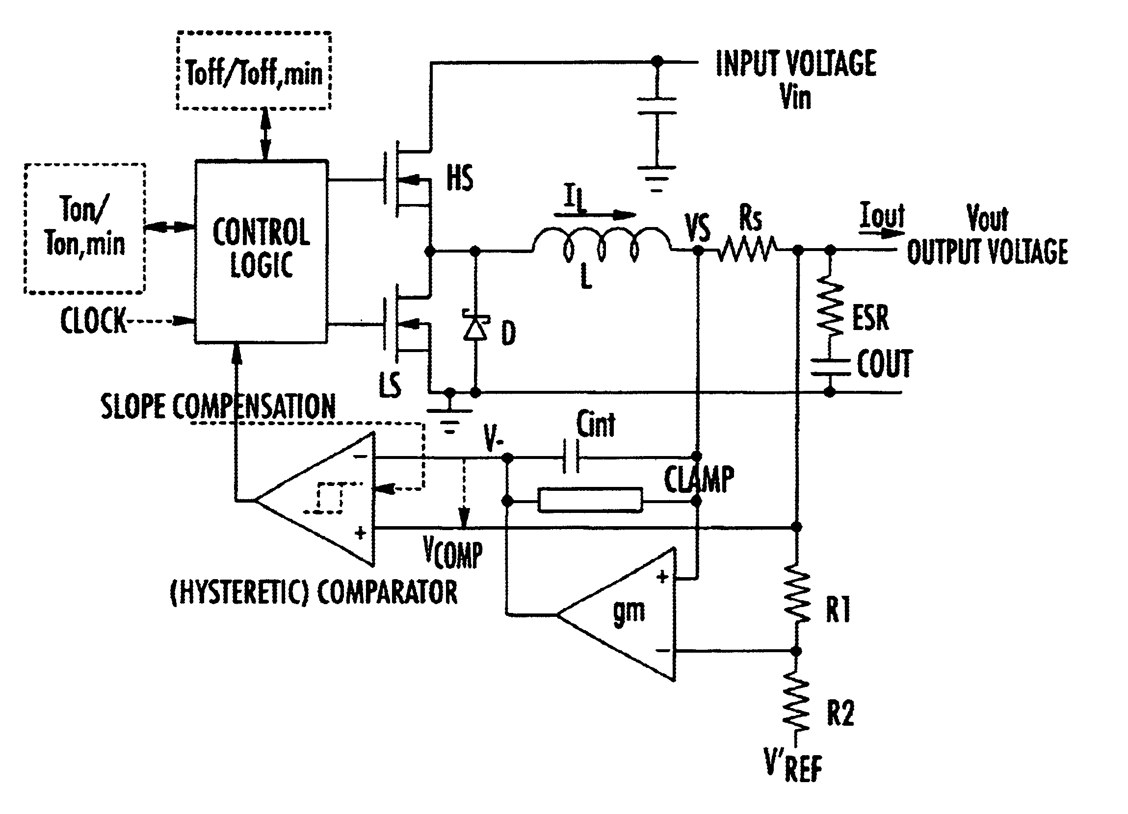
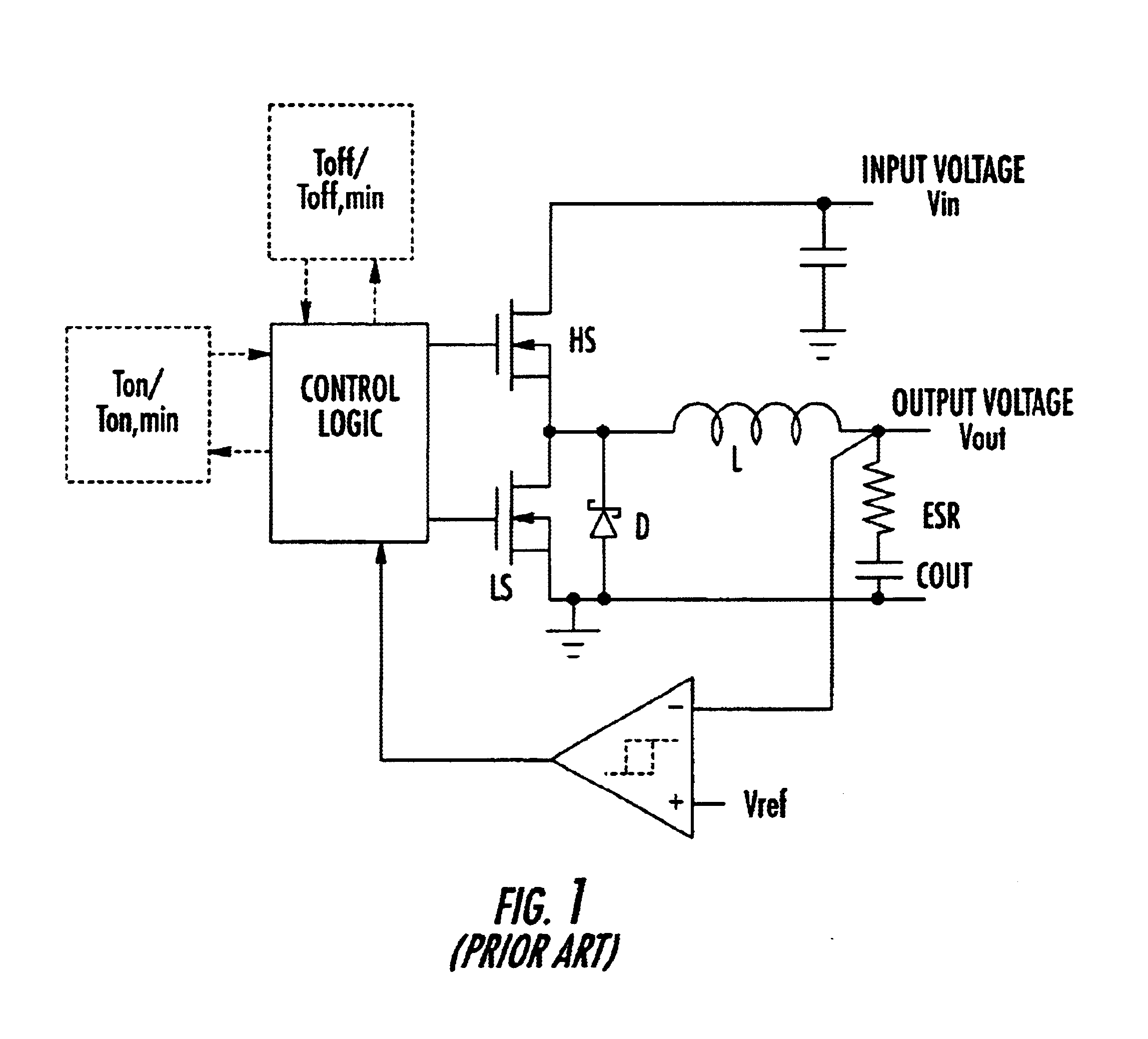
[0065]Two embodiments of the regulator of this invention are depicted in FIGS. 7 and 8. For the purpose of illustrating how to realize a regulator according to the method of this invention, reference will be made to a step-down regulator. As will be evident to any skilled person, the illustrated circuits may be easily adapted to realize switching regulators of different topology, for instance regulators employing transformers as long as they employ an inductor driven in PWM mode to deliver current to an output capacitor and to a load eventually connected in parallel to the output capacitor.

[0066]A common feature of all the voltage regulator topologies is the presence of an inductance through which, at least during a phase of the cycle, stored energy is discharged towards an output buffer capacitor and thus towards the electric load. For example, in step-up regulators, the current ISW injected in the output capacitor through a switch is the current that flows through the inductor dur...


PUM


Abstract

The method is for regulating the supply voltage of a load via a switching voltage regulator having an inductor driven by at least a power switch for delivering current to an output capacitor having a certain parasitic series resistance, connected between the output node of the regulator and ground and to an electric load eventually connected in parallel to the output capacitor. The method includes establishing a reference voltage, generating a comparison signal as the sum of a first voltage signal proportional to the current circulating in the inductor and of a second voltage signal depending on the difference between the output voltage and the reference voltage and on the first voltage signal. The comparison signal is compared with at least a threshold for generating a logic signal that switches between an active state and an inactive state and viceversa each time that the threshold is crossed, and the turn on or the turn off of the switch is controlled as a function of the state of the logic signal.

Description

FIELD OF THE INVENTION[0001]The present invention relates to voltage regulators, and more particularly to a method of regulation of the supply voltage of a load, a method of operating a regulator and a related voltage regulator.BACKGROUND OF THE INVENTION[0002]Some types of electric loads are subject to rapid variations of the absorbed current. The variation may go from an almost null current to the nominal maximum current and vice versa. The regulator (generally a switching regulator) that supplies these loads must be capable of maintaining the regulated voltage in a pre-defined range of accuracy (dynamic precision), which is often very narrow. For instance, processors used in portable computers supplied by batteries mostly in a stand-by mode during which their consumption is relatively low and from which they resume operation when instructions must be carried out.[0003]The commonly used regulators have a closed loop control of the output voltage VOUT to ensure under steady state c...

Claims


Application Information

Patent Timeline
Patent Type & Authority Patents(United States)
IPC IPC(8): H02M3/04H02M3/156
CPCH02M3/156
Inventor CORVA, GIULIOMARIANI, ADALBERTO
Owner STMICROELECTRONICS SRL
Why Eureka
Try Eureka