Magnetic head suspension with both protected wiring and unprotected wiring, in addition to terminals

a head suspension and terminal technology, applied in the field of magnetic head suspension, can solve the problems of difficult application of liquid photosensitive resin to a shaped workpiece, damage to the suspension opening device, and additional time in the drying process of removing solvent, etc., to achieve satisfactory heat resistance, excellent chemical resistance, and low cost

Inactive Publication Date: 2005-05-17
DAI NIPPON PRINTING CO LTD
View PDF2 Cites 8 Cited by
  • Summary
  • Abstract
  • Description
  • Claims
  • Application Information

AI Technical Summary

Benefits of technology

[0009]The present invention has been made in view of the foregoing problem and it is therefore an object of the present invention to provide a magnetic head suspension provided with a wiring pro

Problems solved by technology

When the suspension opening device, such as an opening tool, is thus inserted in the space between the magnetic head suspensions to set the magnetic head suspensions on the magnetic disk, it is possible that the suspension opening device damages gold-plated wiring parts formed on the inner surfaces of the magnetic head suspensions.
When the wiring protecting layer of the magnetic head suspension is formed by processing the liq

Method used


Image

  • Magnetic head suspension with both protected wiring and unprotected wiring, in addition to terminals
  • Magnetic head suspension with both protected wiring and unprotected wiring, in addition to terminals
  • Magnetic head suspension with both protected wiring and unprotected wiring, in addition to terminals

Examples


example 1

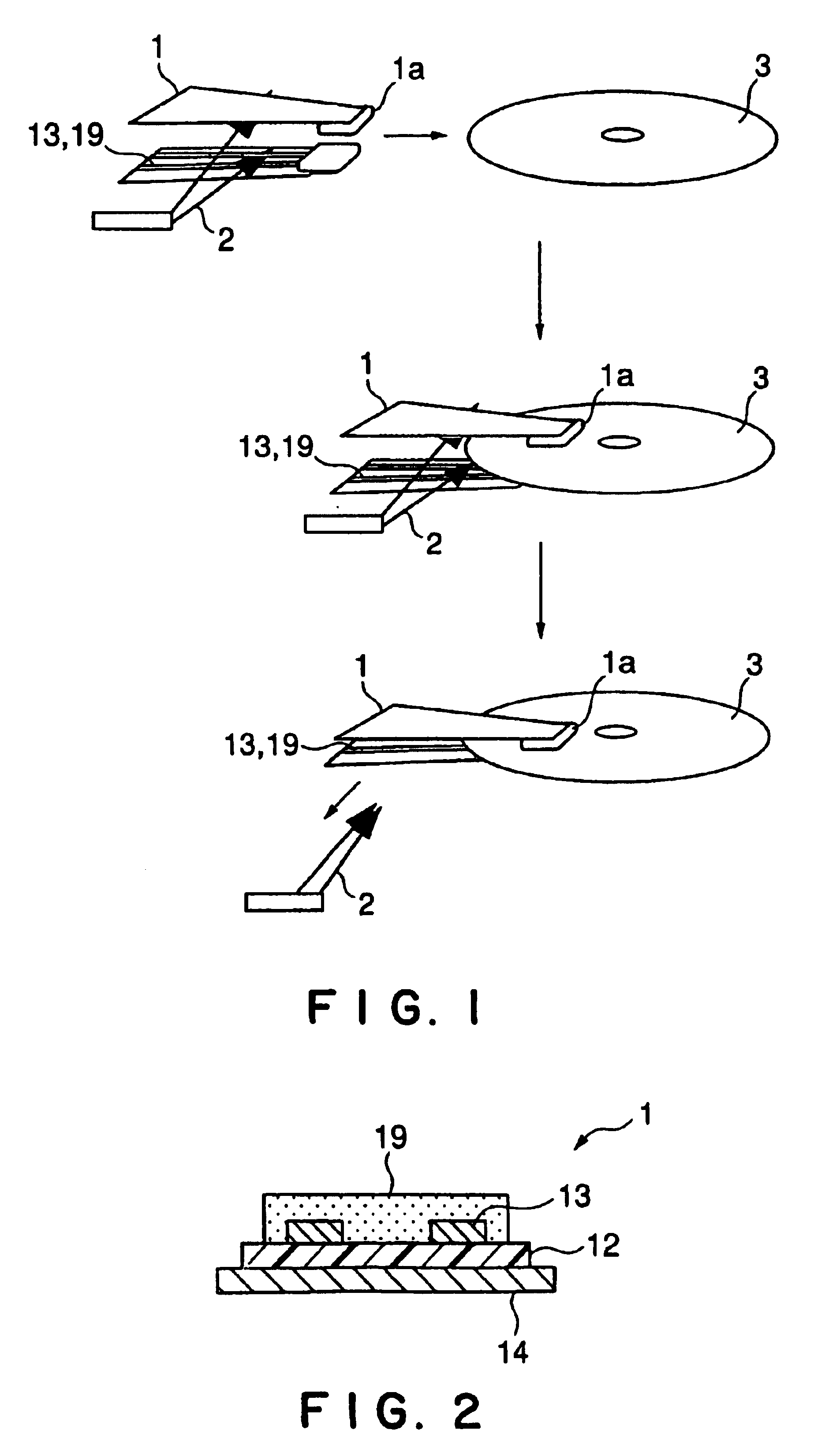
[0062]Magnetic head suspensions in Examples 1 and 2 of the magnetic head suspension 1 shown in FIG. 5 will be described.

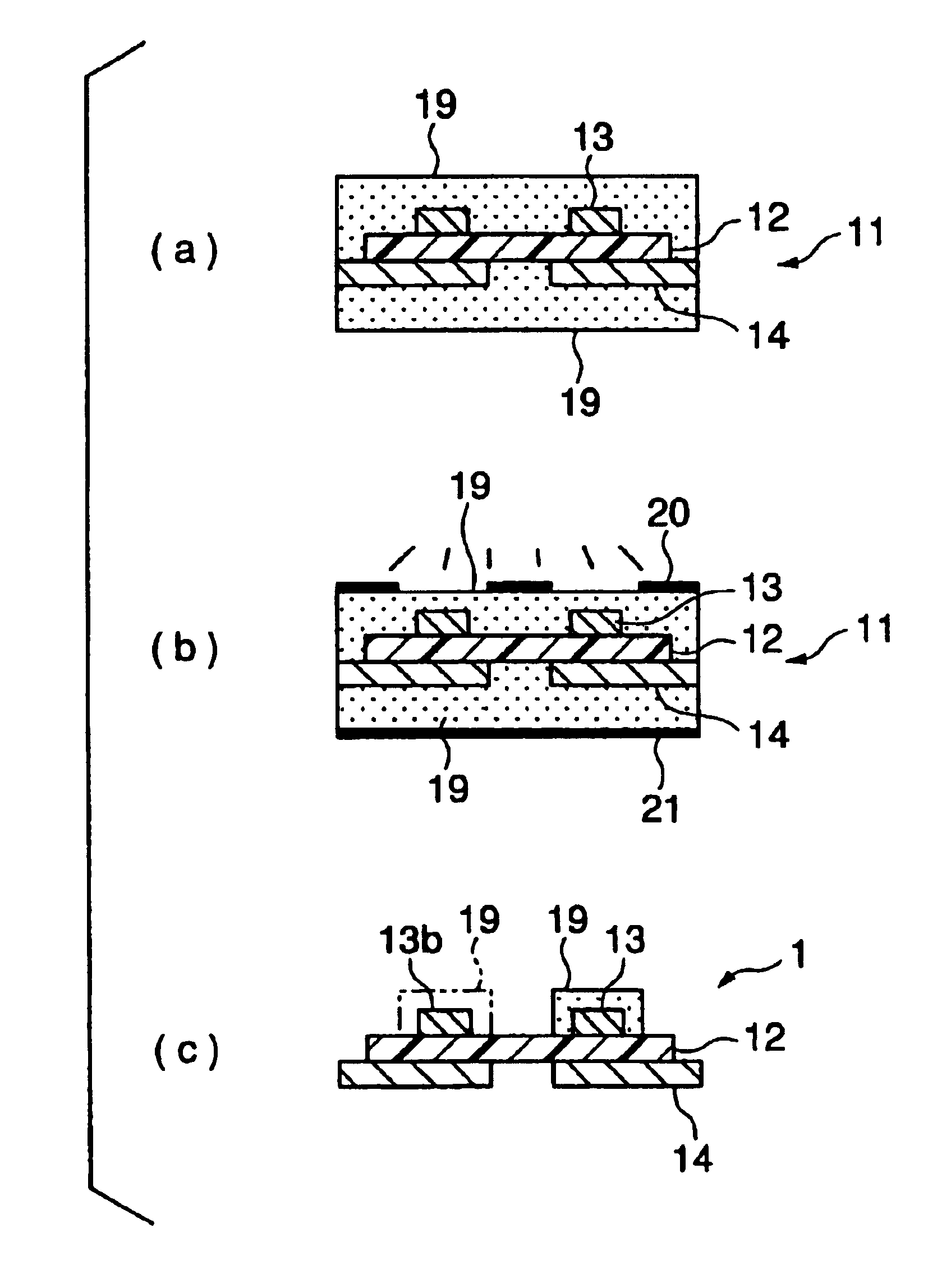
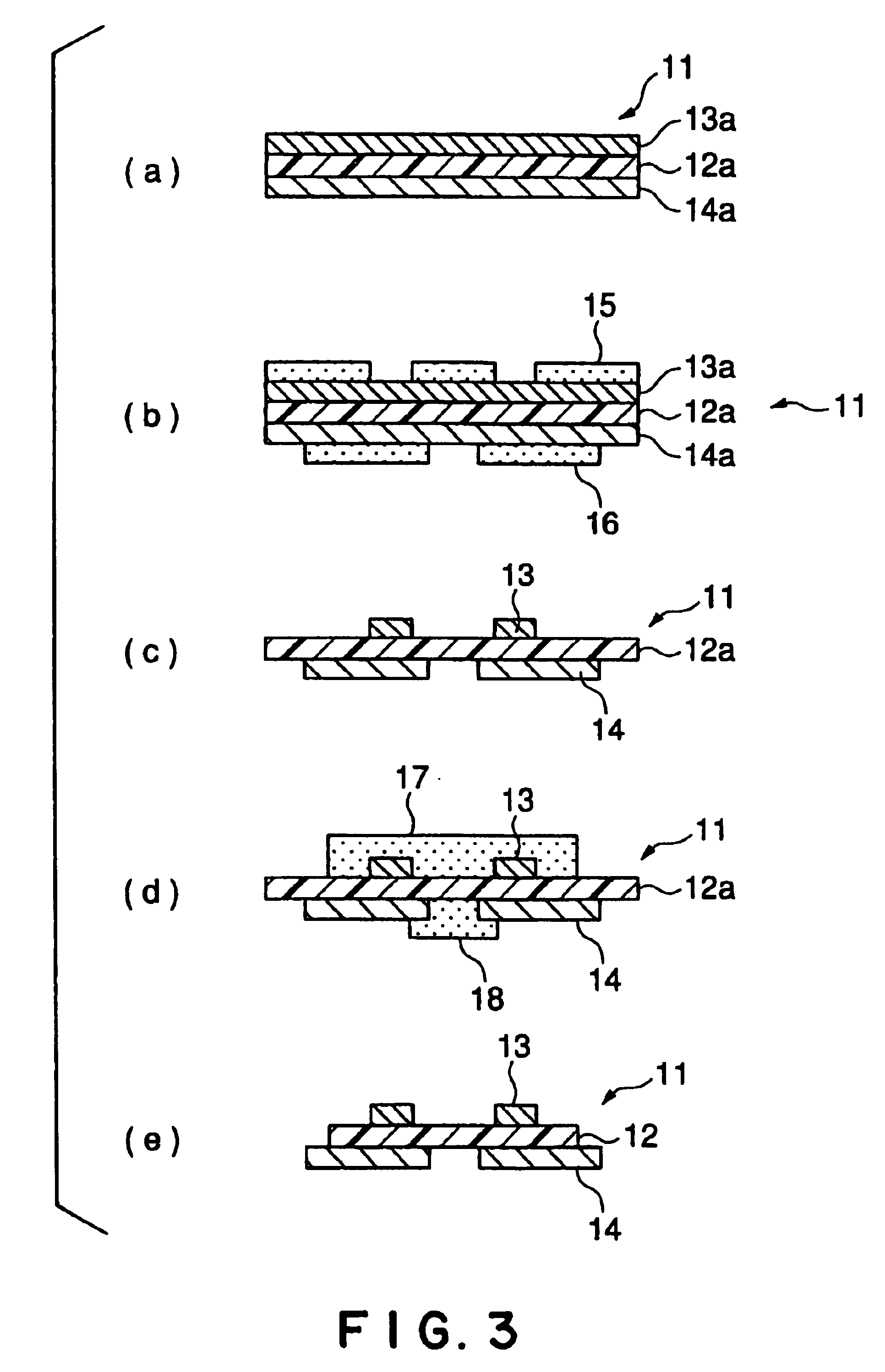
[0063]Photosensitive resin layers of a ultraviolet-curable resin were formed on the opposite surfaces of a three-layer laminated blank 11 consisting of a first metal layer, an insulating layer and a second metal layer, i.e., the surfaces of the first metal layer and the second metal layer. Masks of desired patterns were placed in close contact with the photosensitive resin layers, respectively, and then the photosensitive resin layers were exposed to ultraviolet rays of a wavelength to which the ultraviolet-curable resin was sensitive. The ultraviolet-curable resin was a negative photosensitive resin. Then, unexposed parts of the photosensitive resin layers were dissolved to form etching masks of patterns corresponding to desired shapes on the first and the second metal layer, respectively. Then, the first and the second metal layers were sprayed through the etchin...

example 2

[0069]Photosensitive resin layers of a photosensitive dry film resist were laminated to the opposite surfaces of a three-layer laminated blank 11 consisting of a first metal layer, an insulating layer 12 and a second metal layer, i.e., the surfaces of the first metal layer and the second metal layer. Masks of desired patterns were placed in close contact with the photosensitive resin layers, respectively, and then the photosensitive resin layers were exposed to ultraviolet rays of a wavelength to which the photosensitive dry film resist was sensitive. The photosensitive dry film resist was a negative photosensitive resin. Then, unexposed parts of the photosensitive resin layers were dissolved to form etching masks of patterns corresponding to desired shapes on the first and the second metal layer, respectively. Then, the first and the second metal layers of the laminated blank 11 were sprayed through the etching masks with a ferric chloride solution for etching, and the photosensiti...


PUM


Abstract

A magnetic head suspension includes an insulating base (12), wiring parts (13) formed on one surface of the insulating base (12) including a conductive metal layer, an elastic metal plate (14) provided on the other surface of the insulating base (12), and a wiring protecting layer (19) covering the wiring parts (13). The wiring protecting layer (19) is formed by subjecting a dry film containing an epoxy resin, an acrylic resin and a polymer containing aromatic rings to exposure and developing processes.

Description

BACKGROUND OF THE INVENTION[0001]1. Field of the Invention[0002]The present invention relates to a magnetic head suspension to be employed for a magnetic disk, i.e., a data storage device, and a method of fabricating such a magnetic head suspension.[0003]2. Description of the Related Art[0004]A magnetic head suspension included in a magnetic disk drive operates for reading information from and writing information to a magnetic disk. Magnetic head suspensions with wiring are used prevalently in recent years. Each magnetic head suspension holds a slider at its extremity. When two such magnetic head suspensions are used in combination, the magnetic head suspensions are spaced apart from each other by a suspension opening device, such as an opening tool or a robot arm, the magnetic head suspensions thus spaced apart are advanced toward a magnetic disk, and then the opening tool is removed from the magnetic head suspensions to let the sliders come into contact with the magnetic disk.[000...

Claims


Application Information

Patent Timeline
IPC IPC(8): G11B5/48
CPCG11B5/486
Inventor SERIZAWA, TOORUMOMOSE, TERUTOSHISAKIHAMA, NOBUHIRONAGAI, YOUICHIYAMAZAKI, TSUYOSHIUCHIYAMA, MICHIAKICHIBA, MIDORI
Owner DAI NIPPON PRINTING CO LTD
Why Eureka
Try Eureka