
Engine cooling fan control system

a control system and engine technology, applied in the direction of machines/engines, mechanical devices, clutches, etc., can solve the problems of unnecessary consumption of energy and fuel, and the disadvantageous continued running of the fan, so as to reduce the energy and fuel consumption of the engine

Inactive Publication Date: 2005-05-17
BORGWARNER INC
View PDF4 Cites 12 Cited by
  • Summary
  • Abstract
  • Description
  • Claims
  • Application Information

AI Technical Summary

Benefits of technology

[0003]An object of the present invention is to procure a control system for the fan of a cooling system of an internal combustion engine that eliminates the above-stated disadvantages and reduces the energy and fuel consumption of the engine.
[0007]In an advantageous embodiment of the present invention, the fan is controlled by a control unit to which are fed the setpoint temperature of the cooling system on the one hand, and, on the other, the measured actual temperature of the cooling system. This control unit is connected downstream to the limiter, so that the control unit is active in the usual fashion as long as the ratio of output speed to input speed lies below the specifiable limit. If this limit is exceeded, the limiter prevents an additional increase in the ratio of output speed to input speed and thus limits the performance of the fan. In parallel with the control unit of the downstream limiter, the measured actual temperature of the cooling system is fed to the overheat protection, for which there is specified a critical temperature that is higher than the setpoint temperature specified for the control unit, If this critical temperature is exceeded, a priority logic disables control of the fan via the control unit and the fan can be speeded up to its maximum engagement, at which the ratio of output speed to input speed goes toward 100%.

Problems solved by technology

Disadvantageous continued running of the fan with unnecessary consumption of energy and fuel therefore occurs only in the few cases in which high cooling capacity is actually required.

Method used


Image

  • Engine cooling fan control system
  • Engine cooling fan control system
  • Engine cooling fan control system

Examples


Embodiment Construction

)

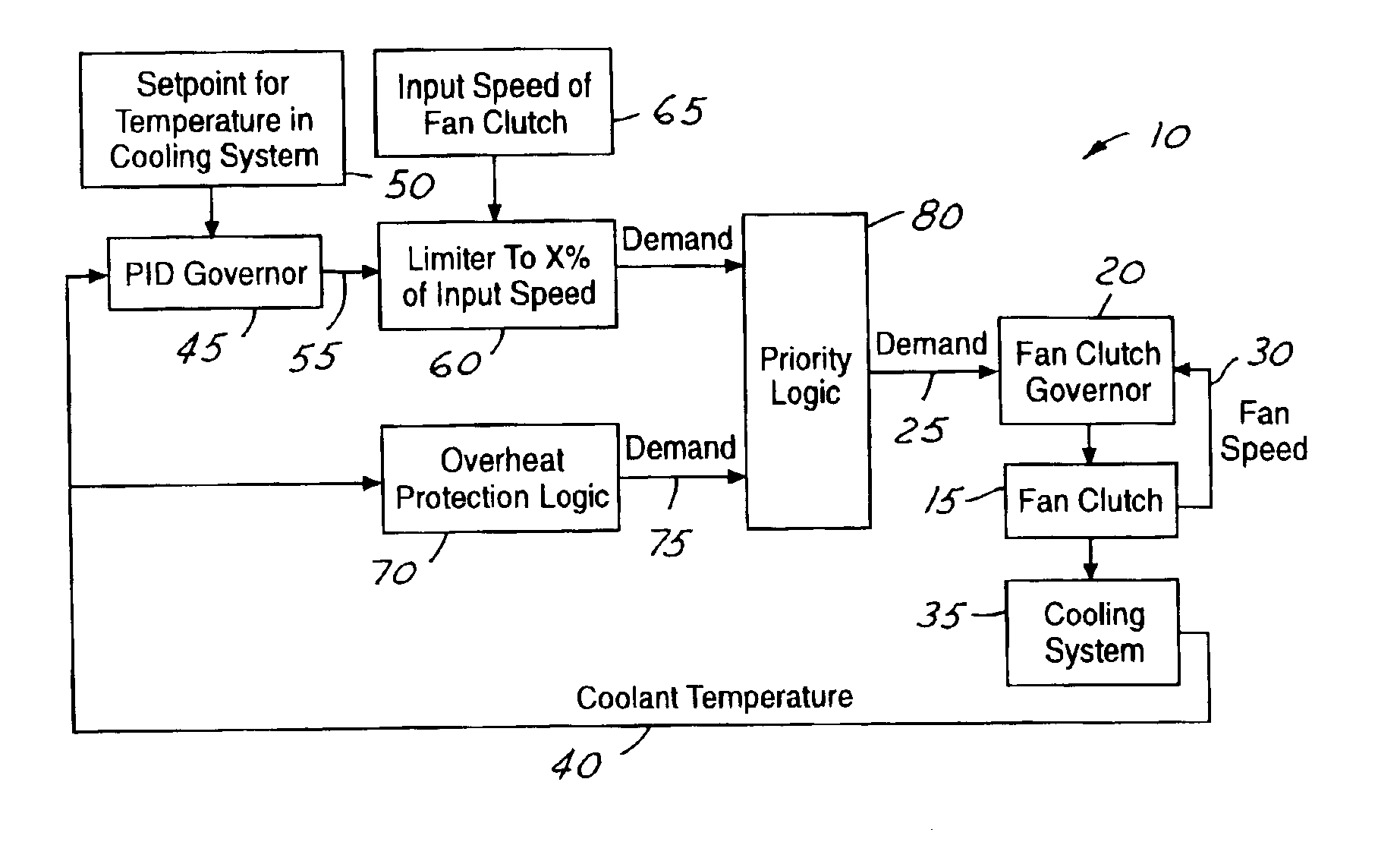
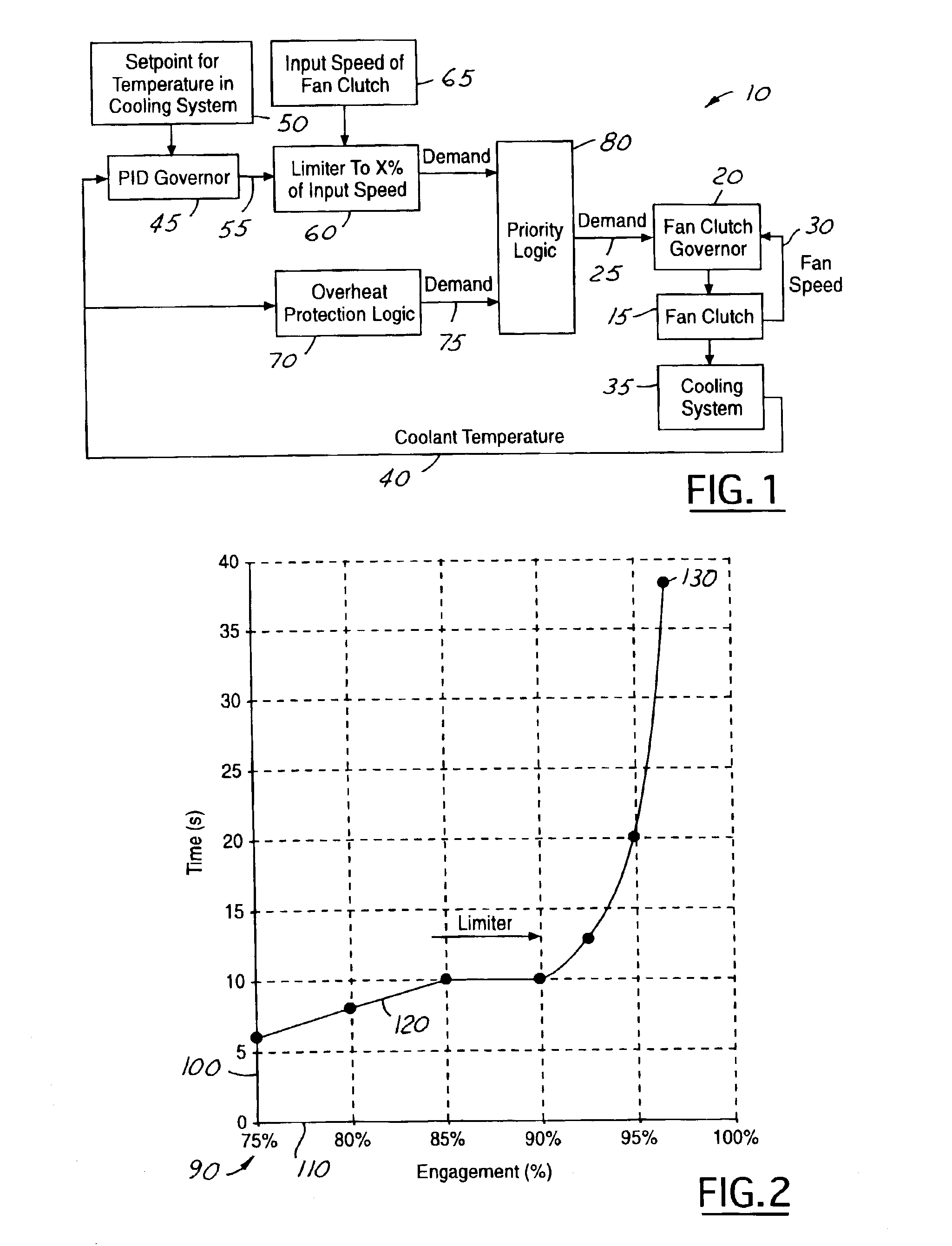
[0012]FIG. 1 is a block diagram of a control system for a fan of a cooling system of an internal combustion engine of a motor vehicle in accordance with an embodiment of the present invention. The system is referred to generally by the reference numeral 10. A fan, not represented, is driven via a viscous coupling (fan clutch) 15. The speed of the fan is controlled in an internal rapid control loop via the coupling (fan clutch). A coupling control unit (fan clutch governor) 20, to which a setpoint speed is fed as the desired value (demand) 25, is used for this purpose. The measured fan speed is fed as the actual tan speed 30 value via a control loop to the coupling control unit (fan clutch governor) 20.

[0013]The fan acts on the cooling system 35 of the internal combustion engine in order to control the temperature of the coolant. The temperature of the coolant in the cooling system is measured and the temperature measurement (coolant temperature) 40 is fed as the actual value to a c...


PUM


Abstract

A control system for a fan of a cooling system of an internal combustion engine of a motor vehicle having a viscous coupling (fan clutch) driving the fan and a control unit (PID governor) to which the setpoint temperature and the measured actual temperature of the cooling system (coolant temperature) are fed. The control unit (PID governor) is connected downstream to a limiter, which holds the ratio of output speed to input speed below a specifiable limit (x % of input speed). An overheat protection logic disables the limiter when the actual coolant temperature exceeds a specifiable critical temperature that is higher than the setpoint temperature of the control unit (PID governor).

Description

TECHNICAL FIELD[0001]The present invention relates to a control system for a fan of a cooling system of an internal combustion engine.BACKGROUND OF THE INVENTION[0002]In a cooling system of an internal combustion engine for motor vehicles having a fan driven by a viscous coupling (fluid coupling), it is known that the temperature of the cooling system may be regulated in that slippage of the coupling is controlled by a control unit. As the need for cooling increases, the degree of engagement of the coupling, i.e., the ratio of output speed to input speed, increases. However, as this ratio increases, i.e., as slippage is reduced, the time that is required in order to pump the viscous fluid out of the chamber of the coupling, and to reduce the degree of engagement of the coupling to a lower required value, increases. This time lag of the viscosity coupling at a high degree of engagement has the disadvantage that the fan continues to run unnecessarily upon a reduction in the engine loa...

Claims


Application Information

Patent Timeline
Patent Type & Authority Patents(United States)
IPC IPC(8): F04D27/02F01P7/04F01P7/00F01P11/16F01P7/02F01P7/08F16D35/02
CPCF04D27/004F01P7/042Y02B30/70F01P7/02
Inventor BUCHHOLZ, THOMAS
Owner BORGWARNER INC
Learn More