Transmission output stage for a mobile telephone

a technology of output stage and mobile telephone, which is applied in the direction of push-pull amplifiers, phase splitters, gated amplifiers, etc., can solve the problems of large loss of useful signal at the fundamental frequency, cost and circuit board area, and the necessary expenditure for filtering harmonics, so as to reduce circuit expenditure and reduce the expenditure for suppressing harmonics.

Inactive Publication Date: 2005-05-17
CINTERION WIRELESS MODULES
View PDF5 Cites 21 Cited by
  • Summary
  • Abstract
  • Description
  • Claims
  • Application Information

AI Technical Summary

Benefits of technology

[0015]The present invention has the following advantages. Due to the push-pull operation for generating the output power at the lower frequency via a push-pull output stage, the first harmonic is already additionally suppressed by 20 . . . 30 dB which considerably lowers the expenditure for suppressing harmonics. Since the power is distributed to two transistors or branches of the push-pull output stage, the same amount of semiconductor material is required as in the single-ended operation with one transistor previously used. During

Problems solved by technology

Such dual-band output stages thus have, for each frequency band, an amplifier optimized for this band which is associated with a considerable expenditure on components and, therefore, with costs and space requirements.
Here, too, the disadvantages are the costs and the cir

Method used


Image

  • Transmission output stage for a mobile telephone
  • Transmission output stage for a mobile telephone
  • Transmission output stage for a mobile telephone

Examples


second embodiment

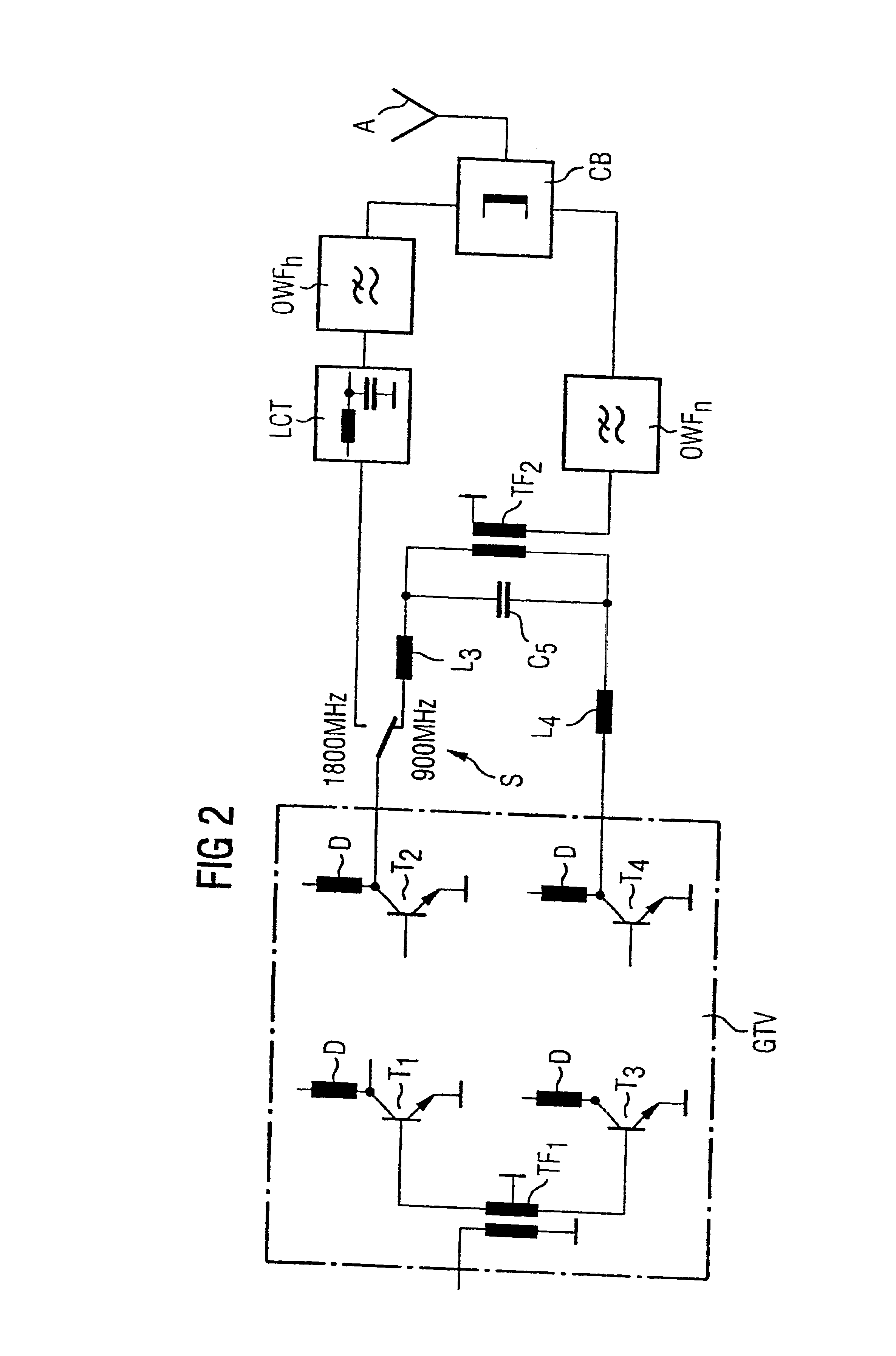
[0021]FIG. 2 shows the transmit stage which differs from the embodiment of FIG. 1 in the output matching circuit. The output signals of the push-pull amplifier GTV here pass to an LC transformer consisting of the inductances L3 and L4 and the capacitance C5, which is followed by a push-pull transformer TF2, in the case of operation at the lower frequency, the switch S being set to the lower position for the 900 MHz operation. This output matching circuit provides for the necessary impedance match to the antenna and for a phase difference of 0° of the signals so that these are combined in the correct phase before the harmonic filter OWF for the low frequency.

first embodiment

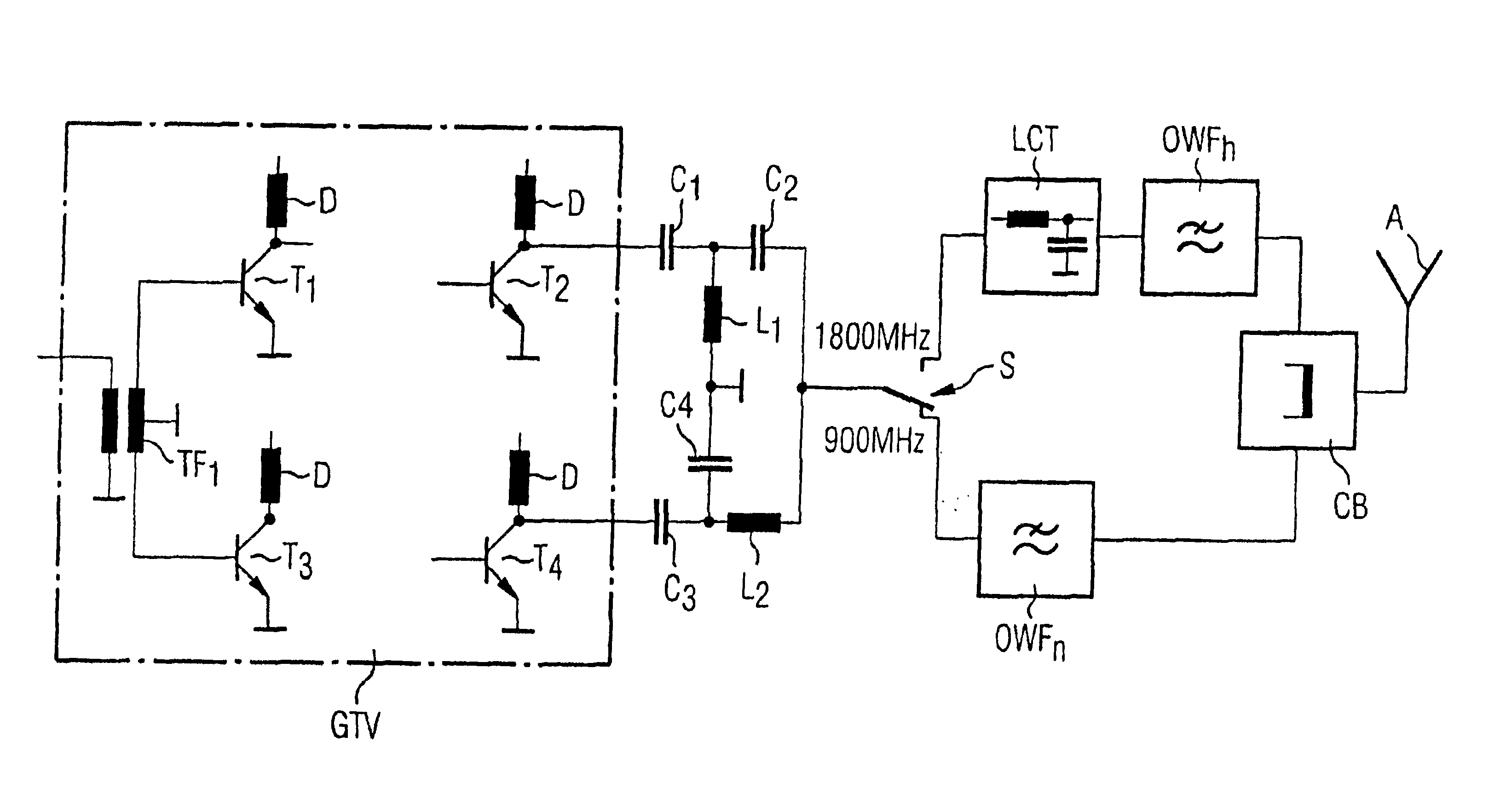
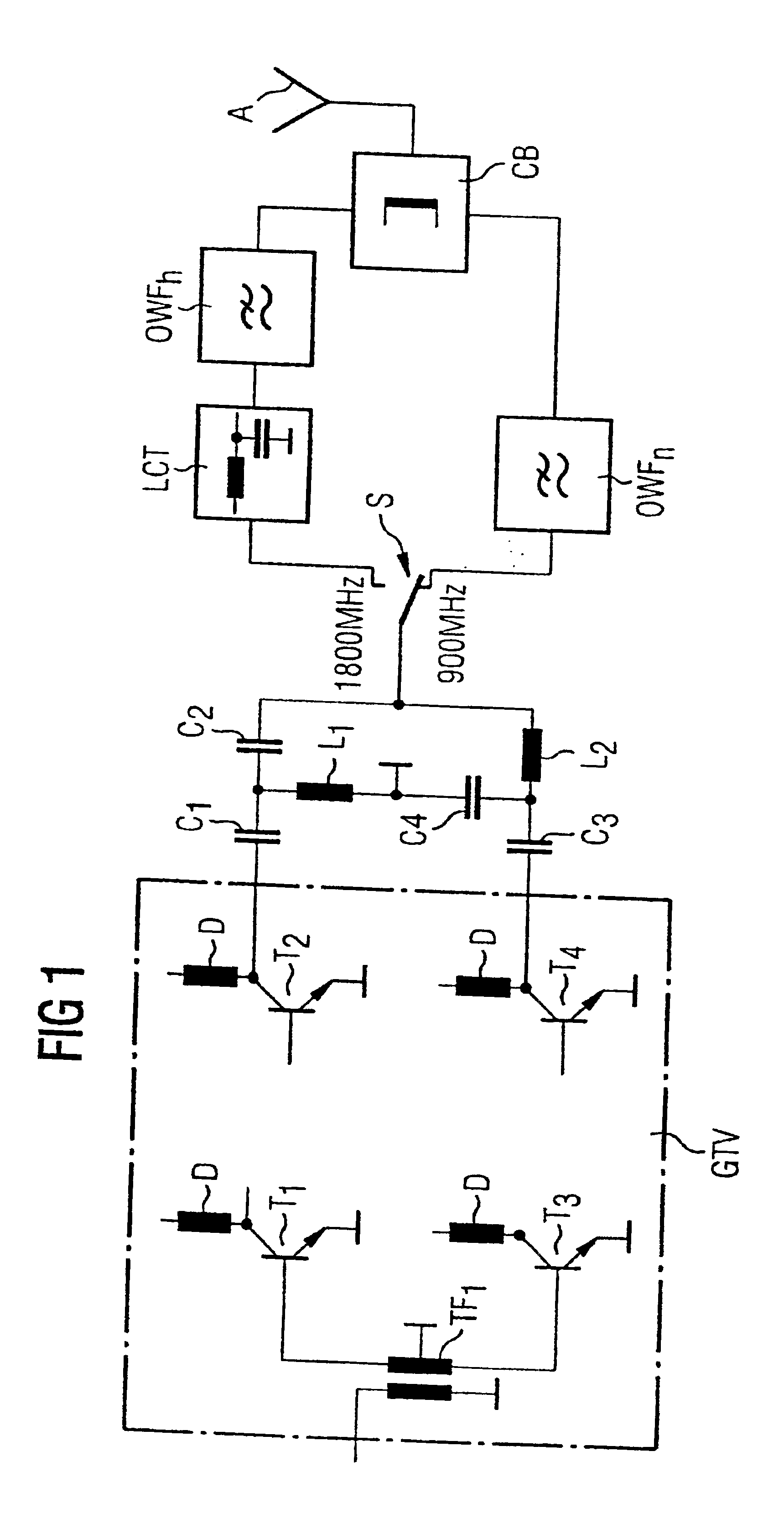
[0022]In the case where the transmission output stage is operated at the high frequency, 1800 MHz in this case, the push-pull amplifier is operated in single-ended mode as in FIG. 1 and the output signal passes via the switch, which is in the 1800 MHz position, directly to the upper branch consisting of an LC transformer LCT and the harmonic filter OWFb for the high frequency.


PUM


Abstract

In a transmission output stage for a multifrequency mobile telephone, the transmit signal of operation at the low frequency is generated by a push-pull output stage which is operated in single-ended mode for generating the transmit signal at the higher frequency.

Description

BACKGROUND OF THE INVENTION[0001]1. Field of the Invention[0002]The present invention relates to a transmission output stage for a mobile telephone and, in particular, to a transmission stage for such a mobile telephone which is designed for two frequency bands.[0003]2. Description of the Prior Art[0004]At present, multiband mobile telephones are being developed and the first types are on the market which can operate at two operating frequencies, that is to say at 900 MHz and 1800 MHz in Europe in accordance with the relevant system definitions, and at 900 MHz and 1900 MHz frequencies in the USA.[0005]First developments operate with narrow-band parallel amplifier chains in the transmit and receive section. Such dual-band output stages thus have, for each frequency band, an amplifier optimized for this band which is associated with a considerable expenditure on components and, therefore, with costs and space requirements. A dual-band output stage of this type having separate amplifie...

Claims


Application Information

Patent Timeline
IPC IPC(8): H03F3/72H03F3/26H03F1/00H04B1/40H03F1/56H04B1/04H04B1/403
CPCH03F1/565H03F3/26H03F3/72H04B1/406H04B2001/0408H04B1/04H03F2200/429H03F3/24
Inventor MOLIERE, THOMAS
Owner CINTERION WIRELESS MODULES
Why Eureka
Try Eureka