Fluidic control of fuel flow

a technology of fluid flow and control device, which is applied in the direction of lighting and heating equipment, machines/engines, and combination engines. it can solve the problems of acoustic vibration and noise, and achieve the effects of noise, and reducing the risk of acoustic vibration

Inactive Publication Date: 2005-05-24
ANSALDO ENERGIA SWITZERLAND AG
View PDF13 Cites 13 Cited by
  • Summary
  • Abstract
  • Description
  • Claims
  • Application Information

AI Technical Summary

Benefits of technology

[0009]By modulating the rate of fuel flow into the combustor it is possible to disrupt a coupling mechanism which is responsible for combustion instability, thereby attenuating the variations in the gas pressure which cause the acoustic vibrations and noise. In practice, the introduction of modulated fuel flow into the combustor effectively prevents the variations in the gas pressure from latching on to certain resonance frequencies at which the acoustic variations and noise are amplified to reach dangerous levels.
[0010]The fluidic oscillator device is preferably an astable (or “flip-flop”) fluidic oscillator. It will be readily appreciated by the skilled person that the astable fluidic oscillator can be of any suitable configuration. As described above, astable fluidic oscillators have no moving parts which means that they are cheap to manufacture and very reliable.
[0011]In a preferred arrangement, the first and second outlet passages diverge from each other in a direction away from the junction and a control inlet communicates with the junction to effect diversion of fuel flow between the outlet passages. The second diverging outlet may be connected to the control inlet by a feedback line that introduces a time delay. The time delay may be increased by means such as a restrictor and / or a volume in the feedback line. The restrictor and / or the volume is / are preferably variable so that the time delay introduced by the feedback line can be varied.

Problems solved by technology

By modulating the rate of fuel flow into the combustor it is possible to disrupt a coupling mechanism which is responsible for combustion instability, thereby attenuating the variations in the gas pressure which cause the acoustic vibrations and noise.

Method used


Image

  • Fluidic control of fuel flow
  • Fluidic control of fuel flow

Examples


Embodiment Construction

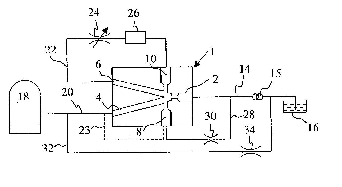
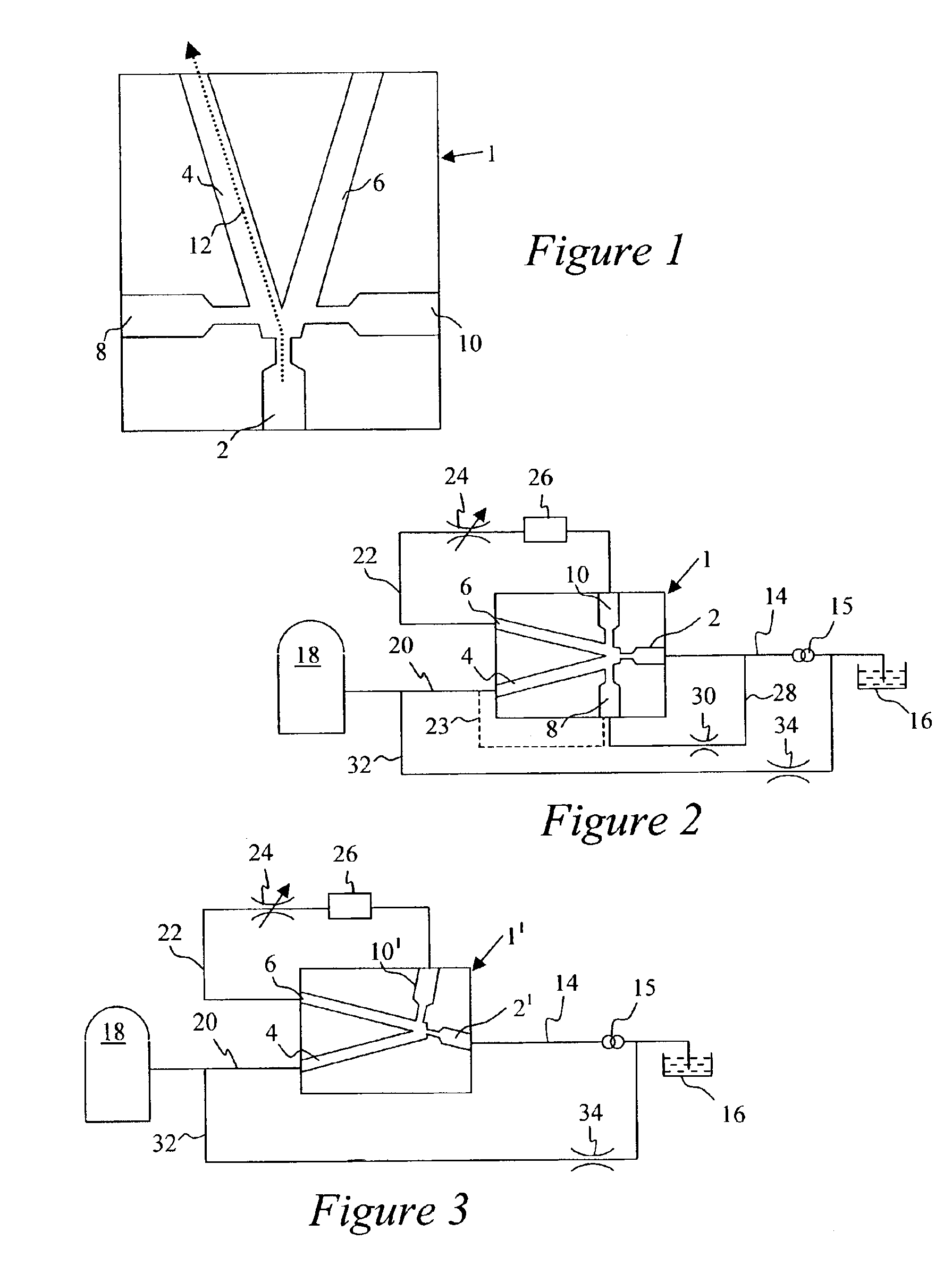
[0026]The present invention will now be explained with reference to FIGS. 2 and 3. FIG. 2 shows a fluidic apparatus including an astable (or “flip-flop”) fluidic oscillator 1 of the sort referred to above. The fluidic oscillator includes a supply inlet 2, a pair of diverging outlets 4, 6 and a pair of oppositely facing control inlets 8, 10.

[0027]A fluid fuel supply line 14 is connected between the supply inlet 2 and a fluid (liquid or gas) fuel source in the form of a fuel tank 16 of a gas turbine engine (not shown). Supply line 14 includes a pump 15 that supplies fluid fuel at a predetermined pressure to the fluidic oscillator 1.

[0028]The left-hand outlet 4 is connected to the combustor 18 of a gas turbine engine (not shown) by means of a fluid fuel discharge line 20.

[0029]The right-hand outlet 6 is connected to the right-hand control inlet 10 by means of a feedback line 22. The feedback line 22 includes a variable restrictor 24 and a downstream volume 26.

[0030]The left-hand contro...


PUM


Abstract

A fluidic apparatus for modulating the rate of fuel flow into the combustor of a gas turbine engine. The apparatus includes a fluidic oscillator device (preferably an astable fluidic oscillator, or “flip-flop”) having a supply inlet connected to a fluid fuel source and a pair of outlets one of which is connected to the combustor. The fluidic device operates to output fluid fuel from the outlets alternately, so modulating fuel flow into the combustor.

Description

TECHNICAL FIELD[0001]The present invention relates to fluidic apparatus, and in particular to fluidic apparatus for use in controlling fuel flow to the combustor of a gas turbine engine.BACKGROUND OF THE INVENTION[0002]All gas turbine engines include a combustor in which a mixture of fuel and air is burnt to produce exhaust gases that drive a turbine. To reduce the amount of harmful emissions such as nitrogen oxides (NOx) that are produced during combustion, most modern gas turbine engines burn a lean pre-mixture of fuel and air, without suppression of NOx by injection of water or steam into the combustion process. However, these sorts of dry low emission (DLE) gas turbine engines are particularly prone to acoustic vibrations and noise caused by variations in the gas pressure within the combustor. These pressure variations can have a frequency of 200 Hz or more, and in larger gas turbine engines the acoustic vibrations and noise can be so severe that the combustor is literally shake...

Claims


Application Information

Patent Timeline
Patent Type & Authority Patents(United States)
IPC IPC(8): F23R3/28
CPCF23R3/28F23D2900/14482F23K2900/05003F23R2900/03281F23R2900/00014
Inventor KNIGHT, PETER HOWARD
Owner ANSALDO ENERGIA SWITZERLAND AG
Why Eureka
Try Eureka