
Apparatus and method for rolling workpieces

a technology of workpieces and apparatuses, applied in mechanical apparatus, crankshafts, manufacturing tools, etc., can solve the problems of significant impairment of reliability and maintainability of the '893 machine, the difficulty of having the cylinders all fit in a compact fashion, and the number of pivotally mounted cylinders providing potential failure points

Inactive Publication Date: 2005-05-24
INGERSOLL CM SYST
View PDF19 Cites 21 Cited by
  • Summary
  • Abstract
  • Description
  • Claims
  • Application Information

AI Technical Summary

Benefits of technology

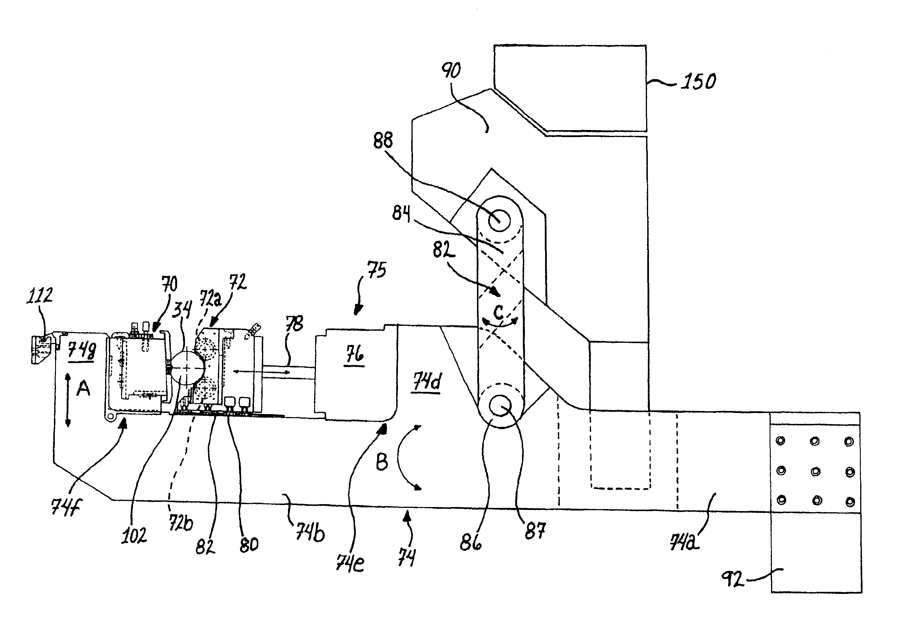
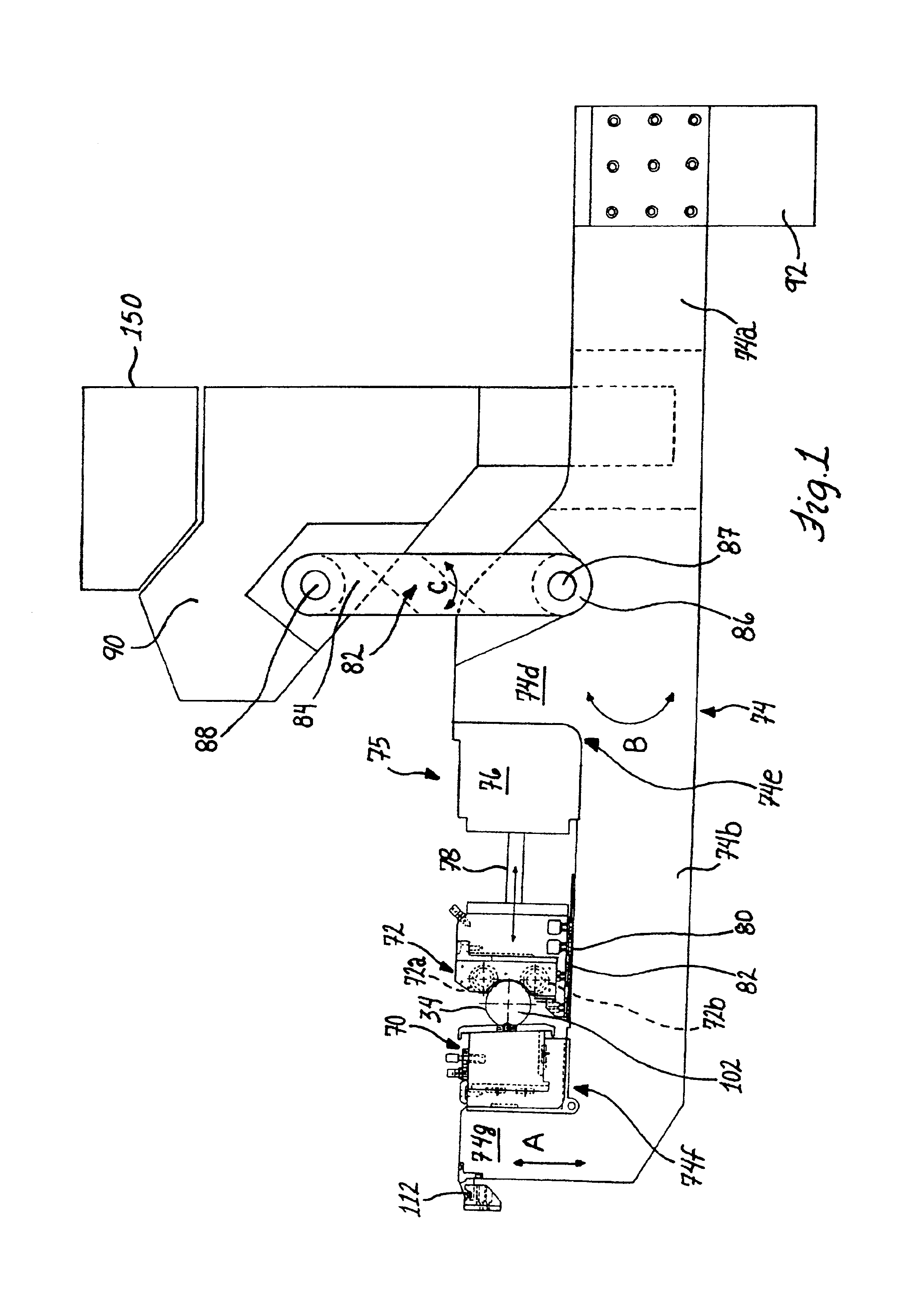
[0008]In accordance with the present invention, there is provided, a new and improved apparatus and method for rolling workpieces such as crankshafts. In one aspect of the invention, the apparatus has first and second rolling heads mounted at spaced positions along a common rolling arm to receive a crankshaft bearing therebetween which can then be shifted relative to one another along the common rolling arm to close the heads or rolling tools for clamping onto the workpiece. This eliminates the need for scissor action levers.
[0009]In accordance with one preferred form of the invention, a drive or motor for shifting the rolling heads relative to each other comprises a power or fluid cylinder mounted on the common rolling arm for shifting the first and second rolling heads relative to each other. In this form, the first rolling head may be fixedly mounted or secured to the common rolling arm and the second rolling head is moved by the drive between the open release position and a closed, rolling position for applying the rolling force to the crankshaft bearing. As such, independent arms for each rolling head are avoided to provide attendant space savings for the present apparatus. Further, the pivot connections and linkages between the arms to provide a scissor clamping action on the crankshaft are not necessary in the present apparatus significantly simplifying its construction and operation enhancing the reliability and maintainability thereof.
[0012]The respective common rolling arms for the respective crankshaft bearings are pivotally mounted to follow the movement of the bearing to which they are clamped, particularly the pin bearings. In the preferred form of the invention, the rolling arms extend generally in a fore and aft direction and are pivotally mounted on support levers that extend transverse to the extending arms. In the illustrated form of the invention, the rolling arms extend generally or substantially in a horizontal direction and the support levers extend at a substantial angle to horizontal, i.e., in a general vertical direction, to allow the clamped rolling heads to travel up and down and forwardly and rearwardly to follow the eccentric path of a pin bearing. The rolling heads, which are following and rolling a main bearing, may shift in a path concentric with the axis of the crankshaft.
[0015]In the illustrated form, the arm positioner includes a body and a vertical slide carrying the selected arm phasing assembly that is motor driven for riding up and down on the body with the body pivoted by a power cylinder. Accordingly, to shift the arms into position for clamping onto all of the bearings of the crankshaft, only one slide member, one motor, and one cylinder is needed in the present invention. This is a vast improvement over prior crankshaft rolling machines that usually have separate cylinders and slides and rod locks for each arm, at least for those that are to roll the pin bearings, such as shown in the '761 patent. Also, there is no need for setting up the machine for each new crankshaft configuration by individual adjustment of each arm as instead once the correct phasing assembly is mounted to the positioner and the rolling arms connected, the remainder of the tool clamping operation is automated as the crankshaft is rotated to its predetermined rotary position under software control, and the arm positioner can then be activated to bring the arms to their operative positions. Further, the crankshaft need not be rotated once in its predetermined rotary position to enable all the bearings to be clamped such as in the machine disclosed in the '893 patent, thus keeping time spent for clamping of the tools onto the crankshaft to a minimum.
[0016]As the rolling head end of the arms are weighted by the rolling tools, preferably a counter-balancing weight is associated with each end of a rolling arm opposite the clamping end having the rolling heads thereon for ease in manipulating and lifting of the arms as may be needed during crankshaft changeover operations by machine operators. Instead of a weight, pneumatic or hydraulic counterbalancing cylinders can be utilized to provide a balanced arm. Each support lever is pivotally connected to the lever arm between the rolling head end and the counterweighted end of the rolling arm and allows its associated rolling arm to oscillate during the rolling operation.

Problems solved by technology

As is apparent, where the crankshaft bearings are very closely spaced, the number of the cylinders and their diameter sizing will make it very difficult to have the cylinders all fit in a compact fashion on one side of the crankshaft without staggering axially adjacent cylinders from each other, or separating the arms that roll the pin bearings from those used to roll the mains such as in the aforementioned '761 patent and as shown in U.S. Pat. No. 5,138,859.
Also, the large number of pivotally mounted cylinders provide potential failure points due to the high number of moving parts and pivot points which may wear and cause seizing of parts.
Accordingly, the reliability and maintainability of the '893 machine is significantly impaired by the large number of pivotal cylinders it employs.
In other words, a machine that needs so many cylinders and pivot connections is much more prone to failure and will require more in the way of maintenance attention and expenses than is desirable.

Method used


Image

  • Apparatus and method for rolling workpieces
  • Apparatus and method for rolling workpieces
  • Apparatus and method for rolling workpieces

Examples


Embodiment Construction

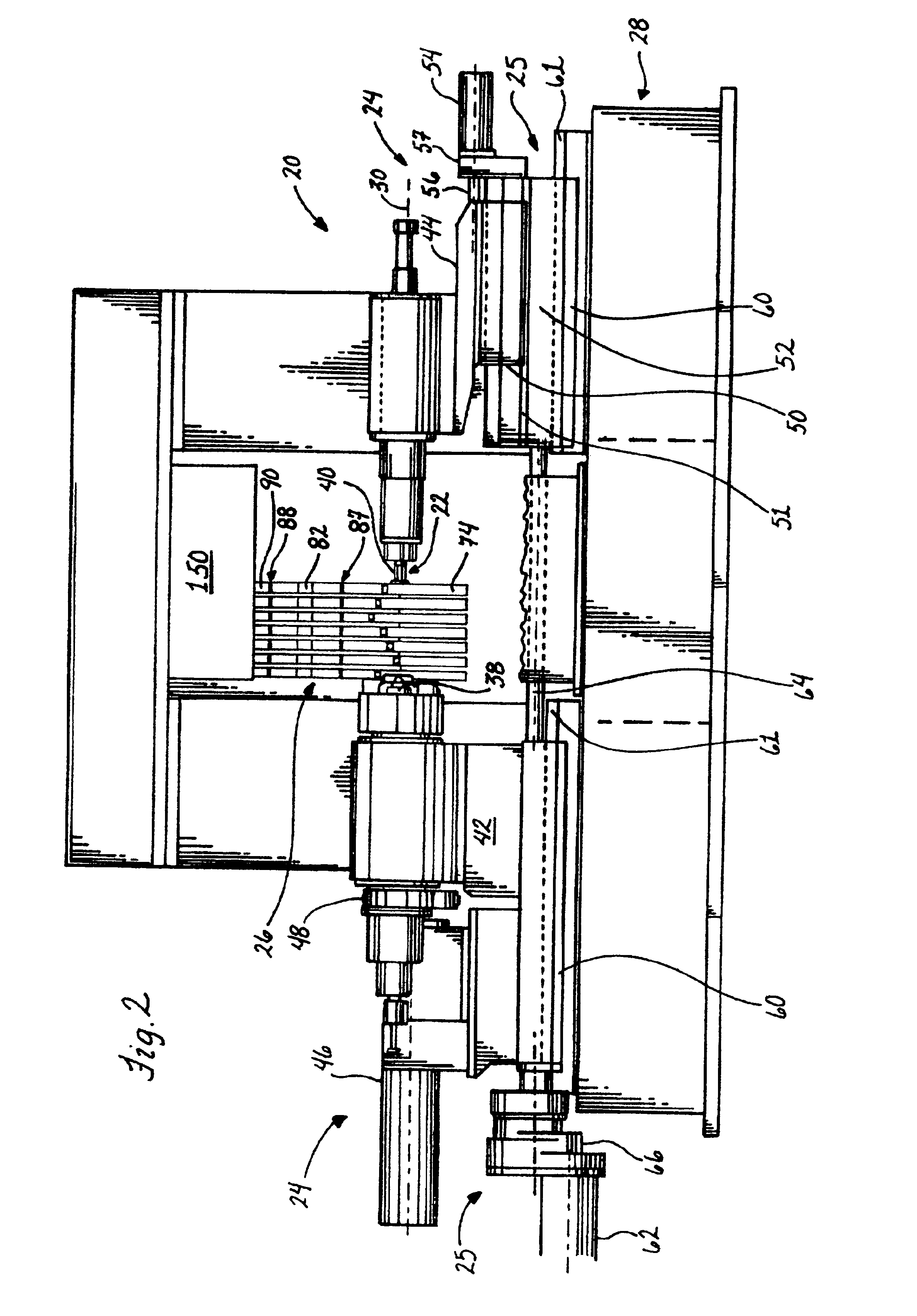
[0059]As shown in the drawings for purposes of illustration, the invention is embodied in a machining apparatus 20 for surface rolling or deep rolling of workpieces such as cam shafts or the like but will be described in connection with the deep fillet rolling of crankshafts 22. As best seen in FIG. 2, the apparatus includes an adjustable workpiece rotational and support device or apparatus 24 for supporting, rotating and positioning of the crankshaft relative a plurality of rolling tool assemblies 26. The tooling assemblies 26 deep roll fillets of the main bearings 32 on the crankshaft (FIG. 5A) and fillets of the pins or pin bearings 34 which can be divided into two groups, as will be described more fully hereinafter.

[0060]The adjustable workpiece support apparatus 24 for supporting the crankshaft and for rotating the crankshaft 22 are mounted on a machine base or frame 28 (FIG. 2). The workpiece support apparatus preferably includes a chuck 38 on a headstock and a tailstock or qu...


PUM

PropertyMeasurementUnit
widthaaaaaaaaaa
distancesaaaaaaaaaa
diameteraaaaaaaaaa

Abstract

There is provided a new and improved apparatus and method for rolling workpieces such as crankshafts. The apparatus has first and second rolling heads mounted at spaced positions along a common rolling arm to receive a crankshaft bearing therebetween which can then be shifted relative to one another along the common rolling arm to close the heads or rolling tools for clamping onto the workpiece. The in-line clamping action and force provided by the tools on the rolling arm are created by actuation of a tall, thin cylinder assembly including a number of aligned individual cylinders sized to keep the width of the cylinder assembly to a minimum so that all of the rolling arms can likewise be of a thin construction pivotally mounted on one side of the crankshaft and axially spaced according to the crankshaft bearing spacing for rolling all of the bearings in a single rolling operation. A strain sensor can be utilized to generate clamping force readouts that are based on the amount of structural deflection of the arm detected by the sensor.

Description

[0001]This application claims the benefit of Provisional Application No. 60 / 252,543, filed Nov. 22, 2000.FIELD OF THE INVENTION[0002]This invention relates to an apparatus and method for surface hardening or deep rolling of a rotating workpiece by rolling devices engaged with the rotary workpiece. This invention also relates to an improved rolling arm apparatus operatively associated with the rolling devices.BACKGROUND OF THE INVENTION[0003]The present invention is directed to a roll hardening apparatus used to surface or deep harden workpieces such as cam shafts and particularly crankshafts having main bearings and pin bearings. As described in U.S. Pat. No. 5,493,761, it is common in current crankshaft roll hardening machines to mount a rolling device such as a rolling head in a fixed position at the end of each of a pair of scissor action type lever arms having a common pivot and to open and close the scissor levers with hydraulic cylinder devices. That is, the hydraulic cylinder...

Claims


Application Information

Patent Timeline
Patent Type & Authority Patents(United States)
IPC IPC(8): B24B39/00B24B39/04B23P9/00B23P9/02B21H7/18B21H7/00C21D7/04C21D7/00
CPCB21H7/185B23P9/02B24B39/045B21H7/182Y10T29/17C21D7/04B23P2700/07
Inventor HEFFRON, ALLAN J.BRECHTELSBAUER, EARL O.ST. PIERRE, MARC D.
Owner INGERSOLL CM SYST
Learn More