Power transmission system

a transmission system and power transmission technology, applied in the direction of mechanical actuation clutches, interengaging clutches, gearing, etc., can solve the problems of affecting the transmission performance, increasing the length of the transmission, and the inability to make the transmission and the power transmission system including the same size,

Inactive Publication Date: 2005-05-24
HONDA MOTOR CO LTD
View PDF11 Cites 12 Cited by
  • Summary
  • Abstract
  • Description
  • Claims
  • Application Information

AI Technical Summary

Benefits of technology

[0033]Preferably, the plurality of transmission paths are paths via a plurality of auxiliary gears which are rotatably arranged on the auxiliary shaft and connected to the output shaft, and have respective different numbers of gears teeth.
[0034]Preferably, the plurality of transmission paths are paths connected to the output shaft via

Problems solved by technology

However, in the conventional power transmission system, it is necessary to arrange the hydraulic shift clutch and the shift cylinder for actuating the same on the input shaft along the same in addition to the synchromeshes so as to prevent the driver from having the inertia travel feeling during an up-shifting operation, which increases the length of the transmission in a direction along the input shaft and hence makes it i

Method used


Image

  • Power transmission system
  • Power transmission system
  • Power transmission system

Examples


first embodiment

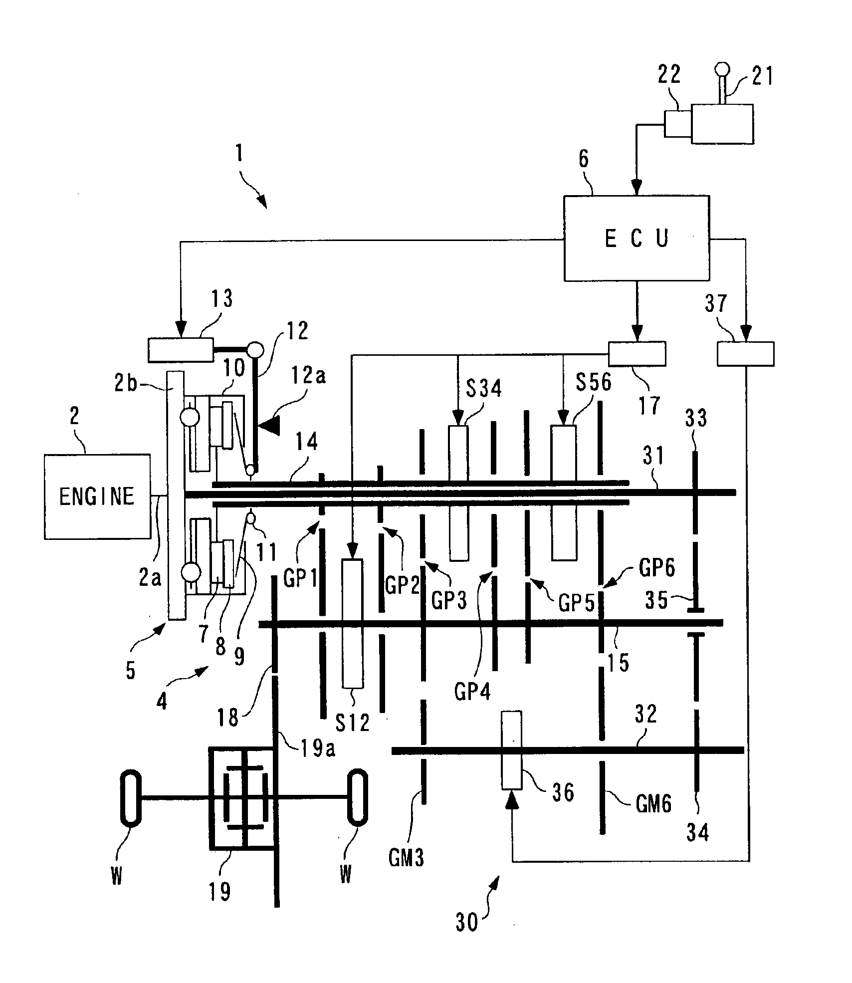
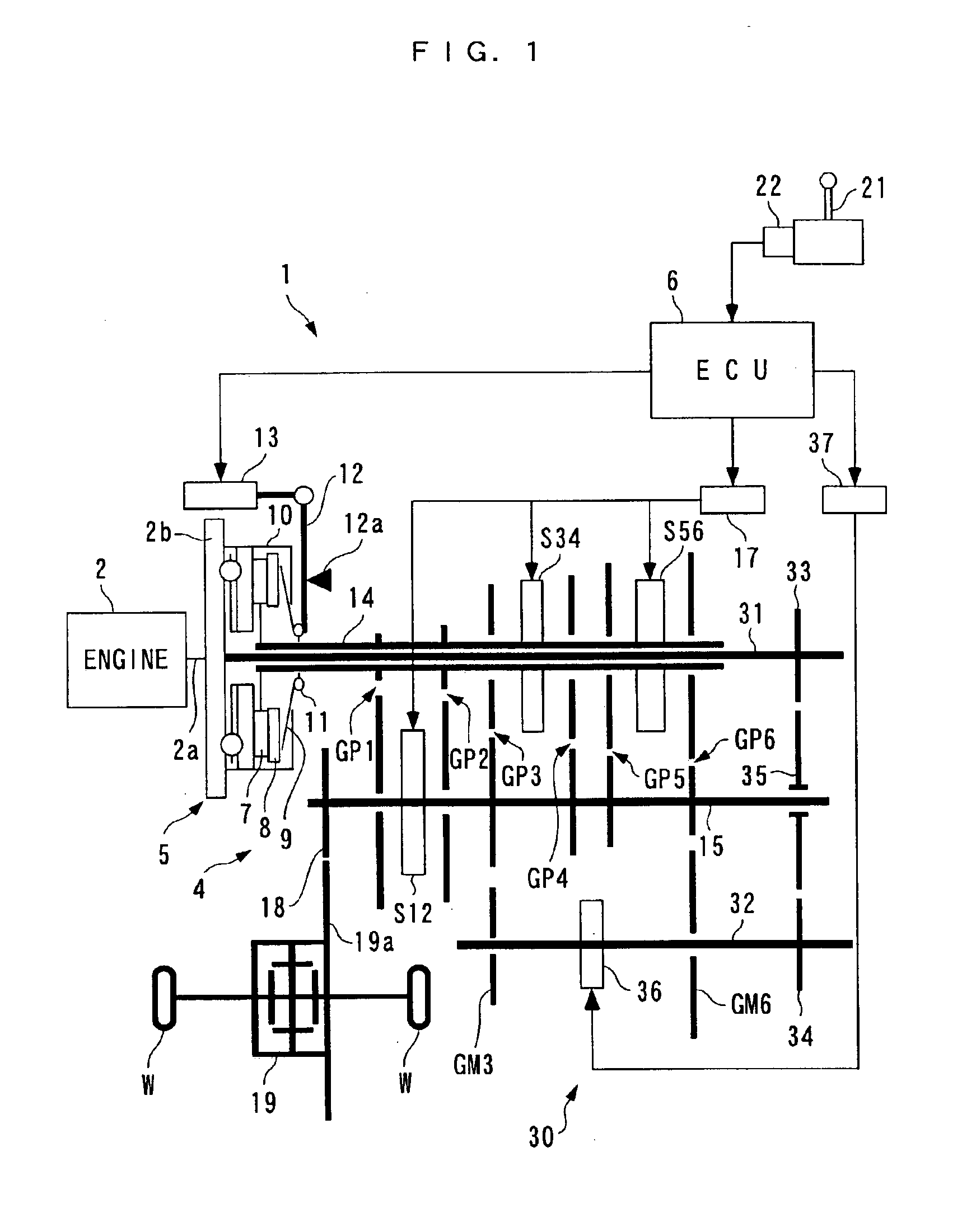
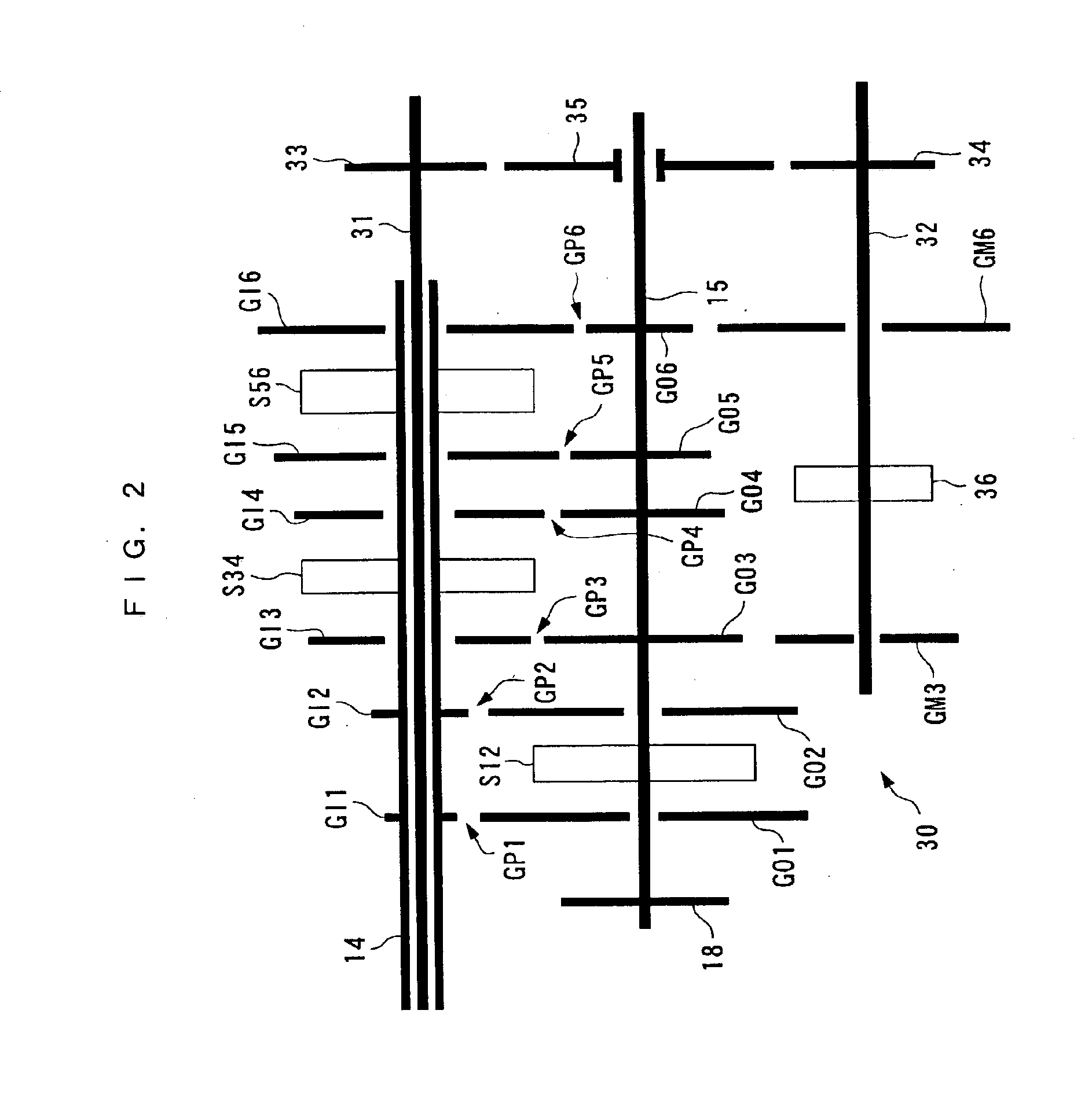
[0088]Therefore, according to the present embodiment, when a shift in speed position is carried out by a transmission 4, the second assist clutch 62 is slid for sliding engagement (connection), whereby the torque of the engine 2 is transmitted from the first auxiliary shaft 31 to the second auxiliary shaft 32, and further supplied to an output shaft 15 via the third speed auxiliary gear GM3 or the sixth speed auxiliary gear GM6 through the connection of the assist clutch 36. Further, by changing the force of sliding engagement (degree of sliding) of the second assist clutch, it is possible to control the magnitude of torque transmitted to the output shaft 15 and the rotational speed of the output shaft 15. This makes it possible to obtain quite the same advantageous effects as provided by the

[0089]FIG. 9 shows a power transmission system according to a third embodiment of the invention. As shown in the figure, the power transmission system according to the present embodiment is dist...

third embodiment

[0097]The operation of the power transmission system 1 according to the present embodiment is basically the same as that of the More specifically, during an up-shift from the first speed position to the second speed position or from the second speed position to the third speed position, a first assist clutch 79 is slid for sliding engagement (connecting), whereby supplemental torque is supplied from the engine 2 to the first output shaft 15a via the first auxiliary shaft 31, the planetary gear mechanism 72, the first auxiliary gear 77, and the second auxiliary gear 78, at a gear ratio slightly smaller than a gear ratio set by the connection of the third speed gear pair GP3. The supplemental torque is then supplied to the differential gear 19 via the second connection gear 82. Further, during an up-shift from the third speed position to the fourth speed position, from the fourth speed position to the fifth speed position, or from the fifth speed position to the sixth speed position,...


PUM


Abstract

A power transmission system is provided which can prevent a feeling of inertia travel due to torque transmission interruption occurring when a dog clutch is engaged to shift the speed position, without increasing the axial length of a transmission. An input shaft is connected to a prime mover via a main clutch. Gear pairs are formed by input and output gears arranged on the input shaft and output shafts, respectively. A dog clutch connects one of the gear pairs to the input or output shaft. An auxiliary shaft is connected to the prime mover. Transmission paths are formed on the auxiliary shaft for transmitting the driving force of the prime mover to the output shaft at different gear ratios. In shifting the speed position, an assist clutch supplies the driving force to the output shaft via the auxiliary shaft and a selected transmission path.

Description

BACKGROUND OF THE INVENTION[0001]1. Field of the Invention[0002]This invention relates to a power transmission system for transmitting a driving force of a prime mover to driving wheels via a stepped transmission.[0003]2. Description of the Prior Art[0004]Conventionally, a power transmission system of the above-mentioned kind has been proposed e.g. by Japanese Laid-Open Patent Publication (Kokai) No. 2000-65199. The power transmission system includes a five-forward-speed transmission having first to fifth speed input gears arranged on an input shaft thereof which is connected to an engine, in the mentioned order from the engine side, and first to fifth speed output gears arranged on an output shaft thereof, in constant mesh with the respective first to fifth speed input gears. These first to fifth speed input and output gears form first to fifth speed gear pairs, respectively. Further, the first and second speed output gears are rotatably supported on the output shaft, and a synchro...

Claims


Application Information

Patent Timeline
IPC IPC(8): F16H3/00B60W10/02B60W10/06F16H3/093F16H3/12
CPCB60W10/06B60W30/18F16H3/12B60W10/02B60K2741/225Y10T74/19233F16H61/682F16H2003/0818F16H2061/0407F16H2061/0425F16H2061/0429F16H2200/0052Y10T74/19219Y10T74/19242Y10T74/19251Y10T74/19284B60W10/10B60W30/1819
Inventor ISHIHARA, SUNAOMATSUDA, KENJIKUMAGAI, TOSHIHARUSUNAGA, ISAMU
Owner HONDA MOTOR CO LTD
Why Eureka
Try Eureka