Magnetic tape cartridge
- Summary
- Abstract
- Description
- Claims
- Application Information
AI Technical Summary
Benefits of technology
Problems solved by technology
Method used
Image
Examples
first embodiment
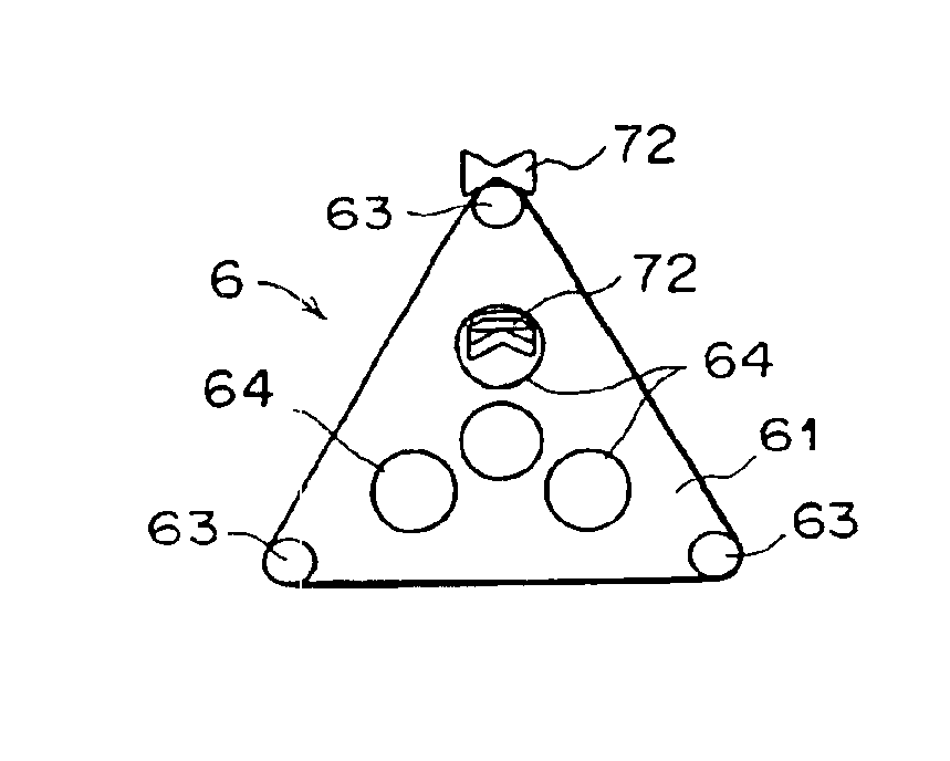
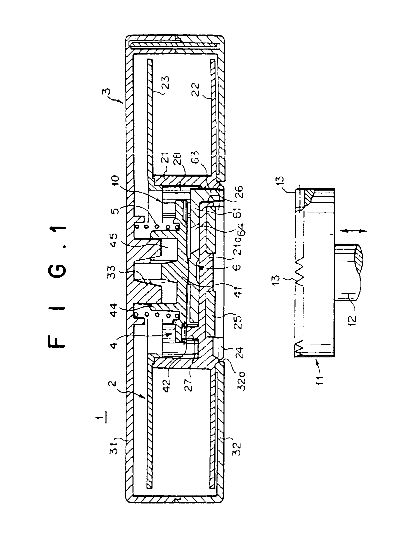
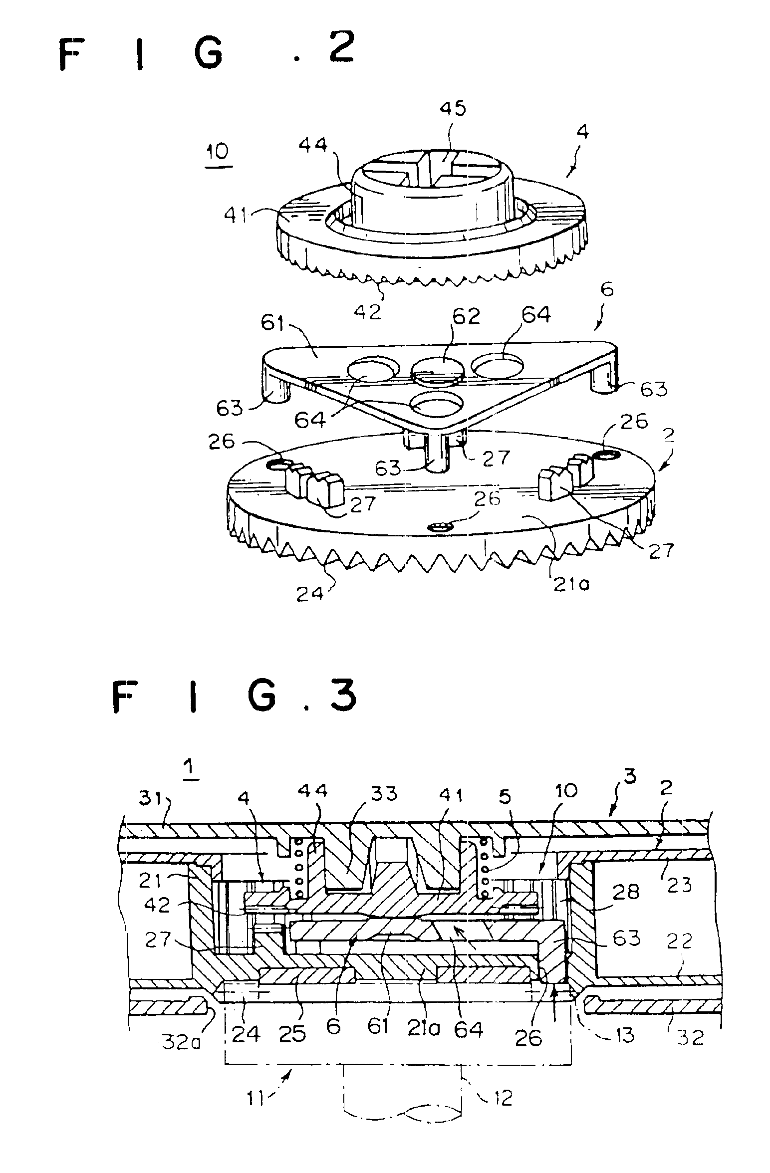
[0078]The present invention will hereinafter be described in detail with reference to embodiments shown in the drawings. FIG. 1 shows a sectional view of a magnetic tape cartridge constructed according to the present invention achieving the aforementioned first object of the invention, the tape cartridge being in an inoperative state. FIG. 2 shows an exploded perspective view of the essential parts of the magnetic tape cartridge of FIG. 1; FIG. 3 shows a sectional view of the essential parts of the magnetic tape cartridge of FIG. 1 being in an operative state; and FIG. 4 shows a plan view of an releasing member being in an assembled state.
[0079]The magnetic tape cartridge 1 is constructed so that a single reel 2 with magnetic tape (not shown) wound thereon is rotatably housed within a cartridge case 3. The cartridge case 3 is formed by fastening an upper case 31 and a lower case 32 which has a center opening 32a, with small screws, etc. The magnetic tape cartridge 1 is equipped with...
second embodiment
[0109]the leader tape 107 is constructed so that the base film of the leader tape 107 has a lengthwise elastic modulus of 630 kg / mm2 or less and a widthwise elastic modulus of 580 kg / mm2 or less, preferably a lengthwise elastic modulus of 550 kg / mm2 or less and a widthwise elastic modulus of 550 kg / mm2 or less. For instance, polyethylene terephthalate (PET) film and polyimide (PI) film are suitable for the base material of the leader tape 107. If a base material whose elastic modulus (Young's modulus) is relatively low is used, the tear strength for the leader tape 107 becomes higher. Even if it is repeatedly used, there will be no damage and excellent reliability will be obtained. A base material whose elastic modulus is high is liable to tear by contact with an edge portion.
third embodiment
[0110]the leader tape 107 is constructed so that the thickness of the leader tape 107 is less than or equal to 5 times that of the magnetic tape 104. That is, as shown in FIG. 11, at the part where the magnetic tape 104 and the leader tape 107 are joined together by the splicing tape 107a, the thickness b of the leader tape 107 is greater than the thickness a of the magnetic tape 104. The dimensions of the magnetic tape 104 and the leader tape 107 are set so that a ratio (b / a) between them is 5 times or less (≦5), preferably 3 times or less, and further preferably 2 times or less.
[0111]If the thickness ratio between the magnetic tape 104 and the leader tape 107 is made relatively small, the stepped portion in the joint portion between them can be made smaller; the tape transfer onto the stepped portion due to deformation caused by winding of the magnetic tape 104 can be reduced; a tape end region, which has a possibility of dropout and in which no magnetic recording is performed, ca...
PUM
 Abstract
Description
Claims
Application Information
 - R&D
- Intellectual Property
- Life Sciences
- Materials
- Tech Scout
- Unparalleled Data Quality
- Higher Quality Content
- 60% Fewer Hallucinations
Browse by: Latest US Patents, China's latest patents, Technical Efficacy Thesaurus, Application Domain, Technology Topic, Popular Technical Reports.
© 2025 PatSnap. All rights reserved.Legal|Privacy policy|Modern Slavery Act Transparency Statement|Sitemap|About US| Contact US: help@patsnap.com


