Method for transmural ablation

a transmural ablation and catheter technology, applied in the field of transmural ablation, can solve problems such as severe complications, and achieve the effect of reducing unnecessary damage to the heart tissu

Inactive Publication Date: 2005-05-24
ATRICURE
View PDF325 Cites 120 Cited by
  • Summary
  • Abstract
  • Description
  • Claims
  • Application Information

AI Technical Summary

Benefits of technology

[0025]More specifically, the invention comprises a method for at least partially electrically isolating a pulmonary vein from a heart atrium comprising the steps of clamping together the opposed walls of the atrium proximal to the pulmonary vein so that the opposed walls are in contact with each other along a line. The tissue in both walls along the line of contact is then ablated to form a corresponding line of ablated tissue without bonding the walls together. Clamping of the tissue insures that the ablation element is fixed with respect to the tissue intended for ablation. Clamping of the tissue between the RF electrodes minimizes the tissue being ablated because the volume of the tissue in a direct path between the electrode is minimized. The energy is more concentrated because the two poles are close together. These steps are performed a plurality of times, each time partially circumscribing the pulmonary vein, with the steps being performed a sufficient number of times to form a series of lines that substantially fully circumscribe the pulmonary vein. Preferably, the method is performed in a single step, with a continuous lesion being formed that circumscribes one or both of the pulmonary veins. If one or both pulmonary veins are isolated in a single step, the blood flow through the veins is cut off. If the blood flow through the pulmonary veins is cut off for several minutes, severe complications can result as a result of the blood stasis, including clotting within the veins. The delivery of RF energy through the clamped tissue is extremely rapid, typically less than 30 seconds, because the volume of ablated tissue is minimized, and the energy concentration is maximized. If a sequence of overlapping lesions is created to isolate the pulmonary veins, then the blood flow is not cut off, and the problems associated with the blood stasis are avoided.

Problems solved by technology

If the blood flow through the pulmonary veins is cut off for several minutes, severe complications can result as a result of the blood stasis, including clotting within the veins.

Method used


Image

  • Method for transmural ablation
  • Method for transmural ablation
  • Method for transmural ablation

Examples


Embodiment Construction

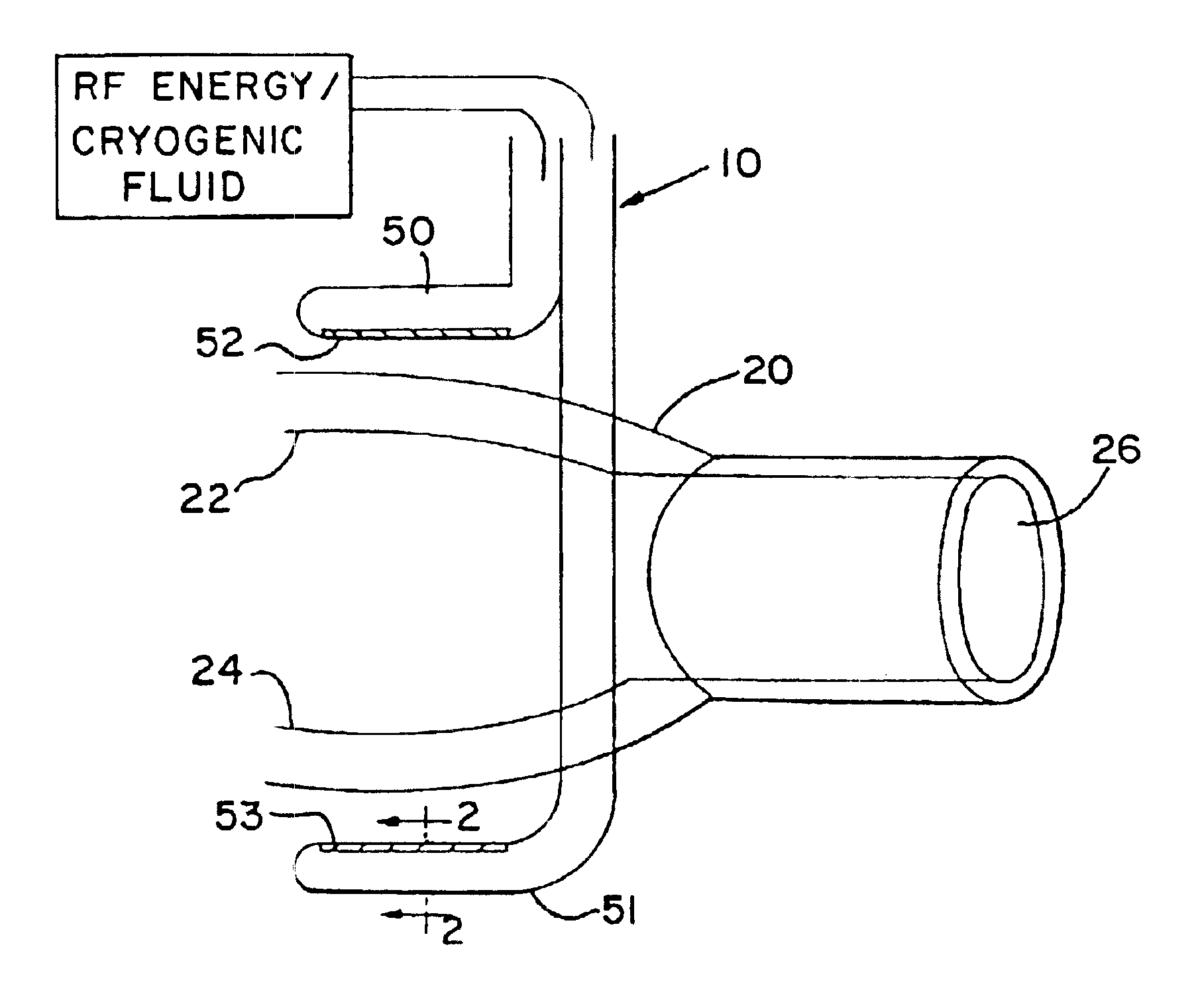
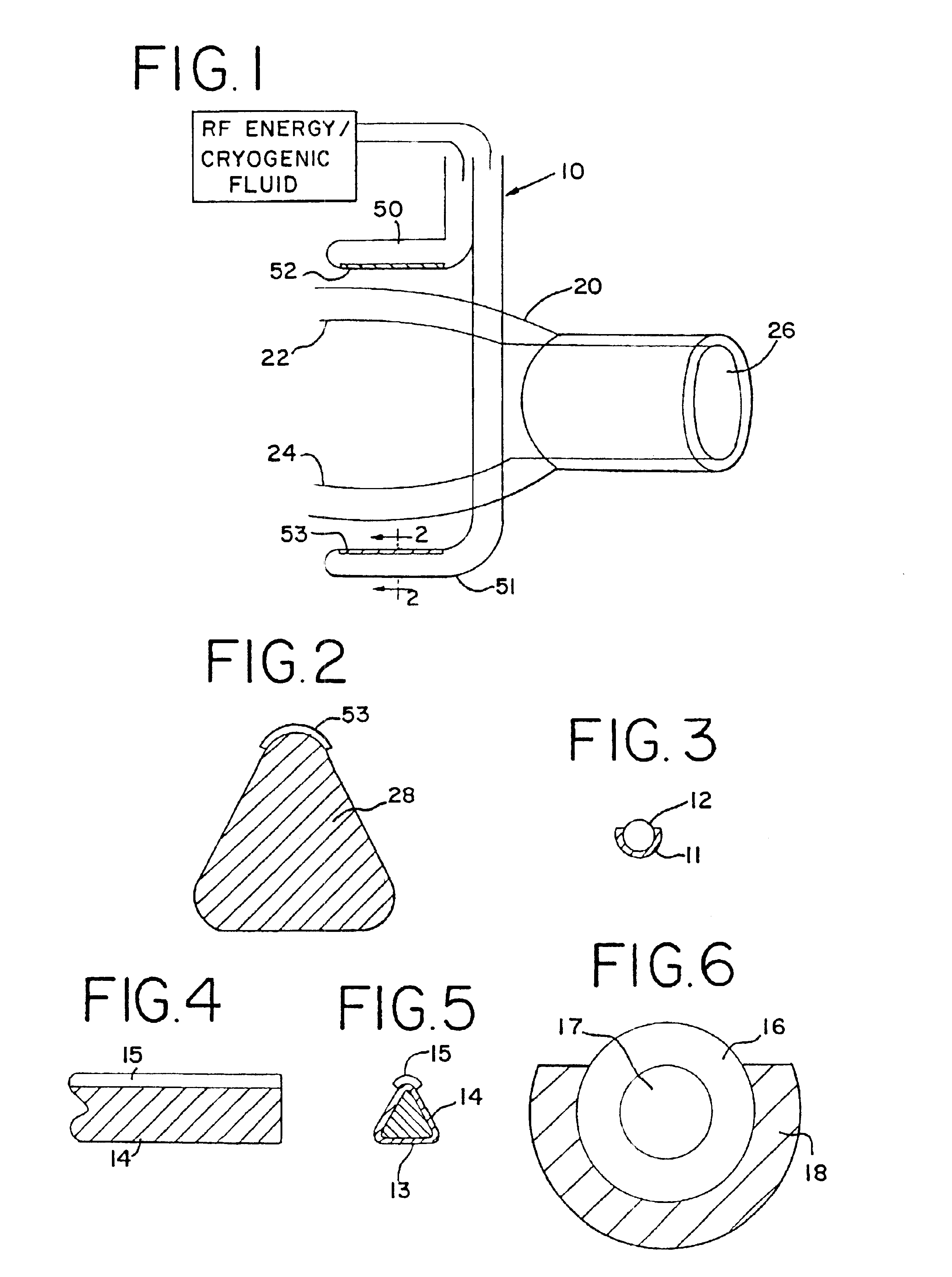
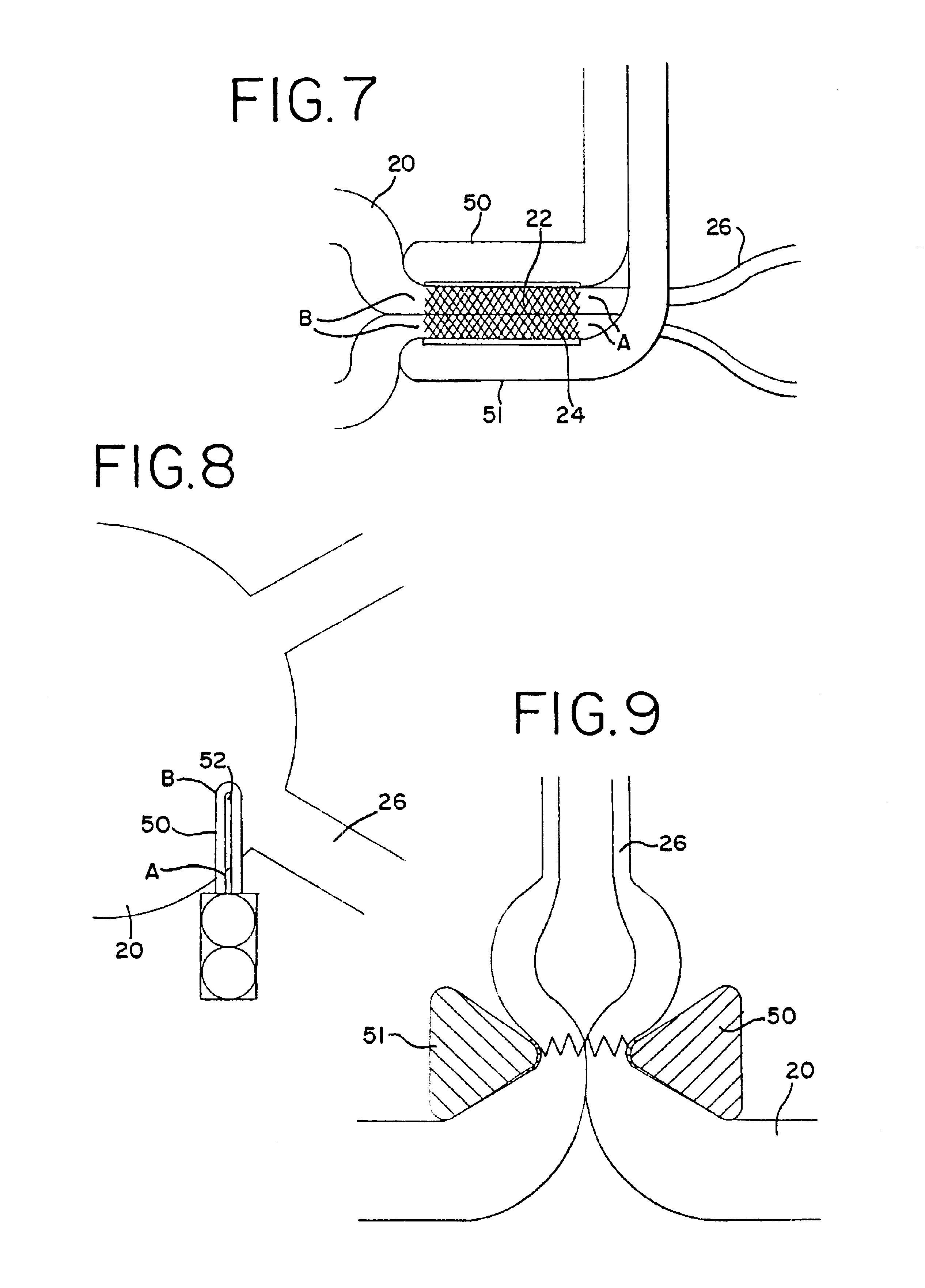
[0040]With reference to the present invention, the compression of the atrial tissue is important because it insures that the exposed electrode surface or cryogenic probe is not in contact with any tissue or blood except the clamped tissue to be ablated. Specifically, the clamping of the tissue between the electrodes or cryogenic probes insures that the conductive or cooled area is only in contact with the clamped tissue. The compressed tissue acts to isolate the electrically active or cryogenically cooled surface, and prevents inadvertent energy delivery to other parts of the heart or blood. The outside temperature of the jaws can easily be monitored to insure that the temperature of the insulation in contact with blood remains below a critical temperature (40° C., for example).

[0041]In one form of the invention, transmural ablation using RF energy is accomplished by providing an atrial ablation device having a lower “j” clamp / electrode element and placing it on the atrial tissue be...


PUM


Abstract

A method for transmural ablation using an instrument containing two electrodes or cryogenic probes. A clamping force is exerted on the two electrodes or probes such that the tissue of the hollow organ is clamped therebetween. Bipolar RF energy is then applied between the two electrodes, or the probes are cryogenically cooled, thus ablating the tissue therebetween. A monitoring device measures a suitable parameter, such as impedance or temperature, and indicates when the tissue between the electrodes has been fully ablated.

Description

CROSS REFERENCE TO RELATED APPLICATION[0001]This application is a continuation of application Ser. No. 09 / 747,609 filed on Dec. 22, 2000, now U.S. Pat. No. 6,546,935 which claims the benefit of provisional application Serial No. 60 / 200,072 filed on Apr. 27, 2000. The above applications are incorporated herein by reference.BACKGROUND OF THE INVENTION[0002]Atrial fibrillation is the most common heart arrhythmia in the world, affecting over 2.5 million people in the United States alone. Ablation of cardiac tissue, in order to create scar tissue that poses an interruption in the path of the errant electrical impulses in the heart tissue, is a commonly performed procedure to treat cardiac arrhythmias. Such ablation may range from the ablation of a small area of heart tissue to a series of ablations forming a strategic placement of incisions in both atria to stop the conduction and formation of errant impulses.[0003]Ablation has been achieved or suggested using a variety of techniques, su...

Claims


Application Information

Patent Timeline
Patent Type & Authority Patents(United States)
IPC IPC(8): A61B18/14A61B17/00A61B18/12
CPCA61B18/1445A61B5/01A61B5/053A61B2017/00026A61B2017/00243A61B2018/145A61B2018/00363A61B2018/00642A61B2018/00755A61B2018/00875A61B2018/1432A61B2017/2945
Inventor HOOVEN, MICHAEL D.
Owner ATRICURE
Why Eureka
Try Eureka