
Hybrid thin film/thick film solid oxide fuel cell and method of manufacturing the same

a fuel cell and thick film technology, applied in the direction of cell components, final product manufacturing, sustainable manufacturing/processing, etc., can solve the problems of high cost of high-performance sofcs, cracking of film after drying, and inability to demonstrate the reduction of commercial practice to da

Inactive Publication Date: 2005-05-24
INTELLIGENT ENERGY LTD
View PDF33 Cites 59 Cited by
  • Summary
  • Abstract
  • Description
  • Claims
  • Application Information

AI Technical Summary

Benefits of technology

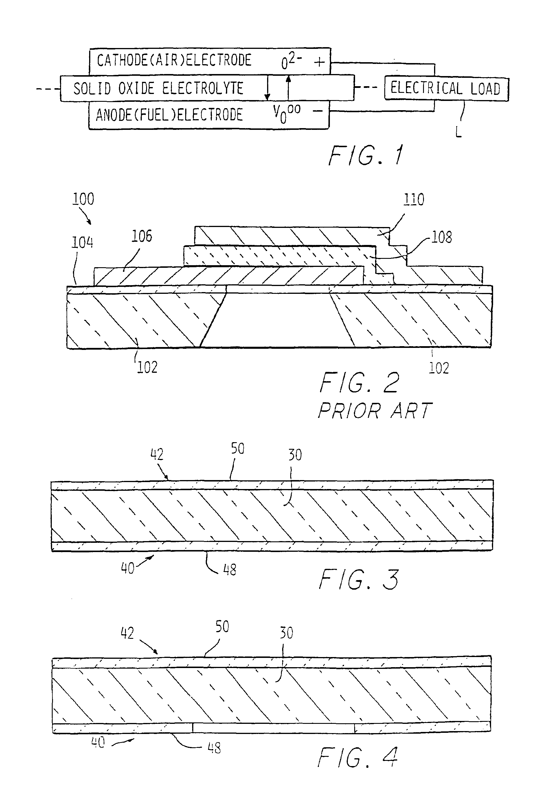
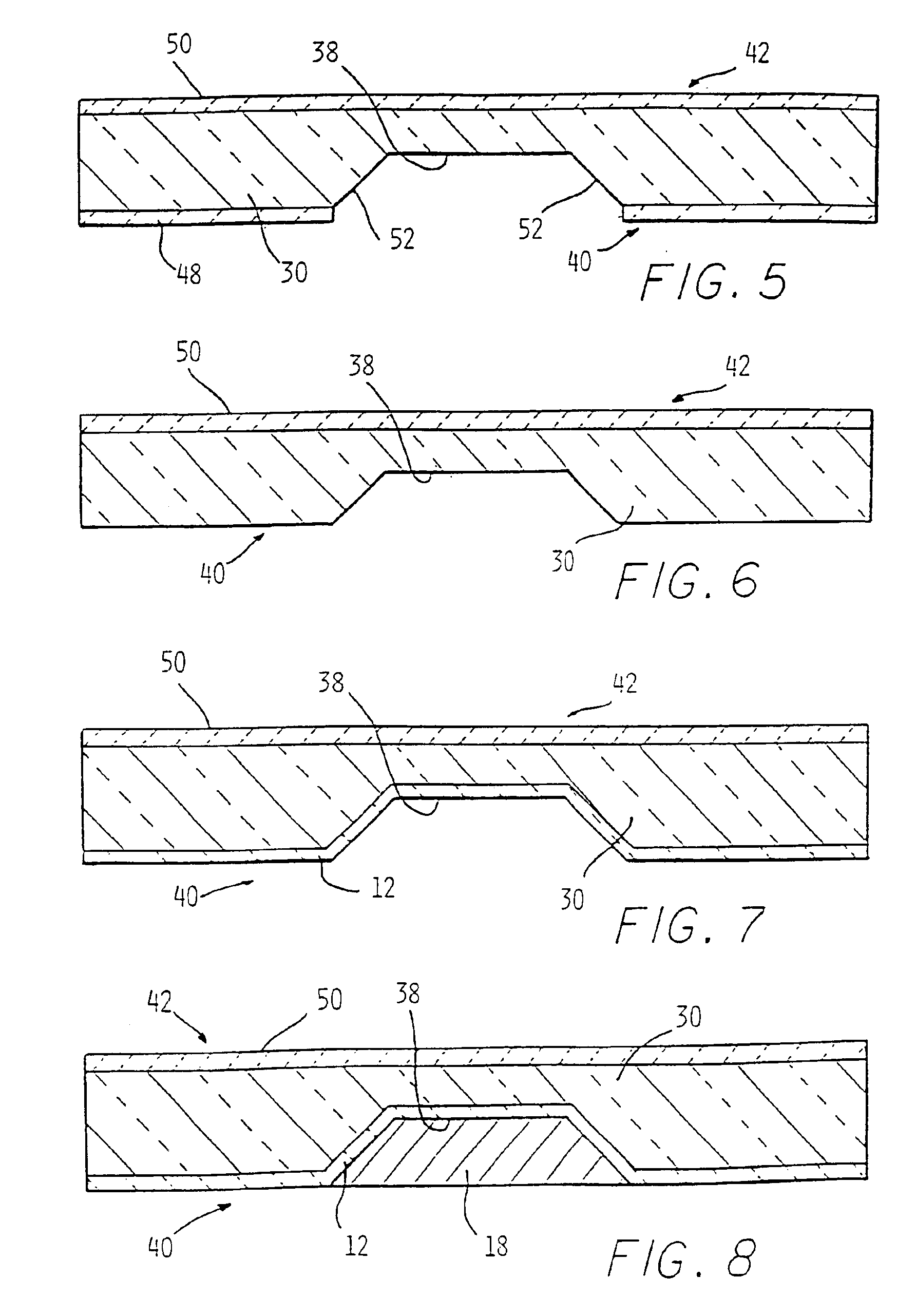
The present invention provides a fuel cell with a thin film electrolyte layer and thick film anode and cathode layers. The fuel cell is made by creating a well in a dielectric or semiconductor substrate and depositing the electrolyte layer on one surface of the well. A counter well is created on the other side of the substrate and a counter electrode layer is applied in it. The technical effect of this invention is to provide a fuel cell with improved performance and efficiency.

Problems solved by technology

Hydrogen represents a challenge for fuel handling and distribution.
Methanol may be promising in a Direct Methanol PEM fuel cell, but a reduction to commercial practice has not been demonstrated to date.
Some researchers have attempted to provide an improved colloidal deposition technique over the prior technique—prior attempts to use colloidal deposition to deposit films thicker than 10 μm in a single step coating had previously resulted in cracking of the film after drying.
Fabrication has generally been recognized to be one of the major problems inherent with SOFC.
These requirements have heretofore rendered successful and cost effective production of high performance SOFCs very difficult.

Method used


Image

  • Hybrid thin film/thick film solid oxide fuel cell and method of manufacturing the same
  • Hybrid thin film/thick film solid oxide fuel cell and method of manufacturing the same
  • Hybrid thin film/thick film solid oxide fuel cell and method of manufacturing the same

Examples


example

[0093]The SOFC 10 of the present invention is fabricated using the following materials. La+Sr+Ga+Mg+O (LSGM)+NiO Cermet is chosen for the anode layer 18. An anode / electrolyte interfacial layer 22 is formed from Sm+Ce+O (SDC). La+Sr+Ga+Mg+O (LSGM) is chosen for the electrolyte layer 12. La+Sr+Co+O (LSC) is chosen for the cathode layer 20. This example of SOFC 10 is a low operating SOFC, with operating temperatures between about 600° C. and about 800° C.


PUM

PropertyMeasurementUnit
thicknessaaaaaaaaaa
thicknessaaaaaaaaaa
thicknessaaaaaaaaaa

Abstract

A SOFC providing higher power densities than PEM-based cells; the possibility of direct oxidation and / or internal reforming of fuel; and reduced SOFC operating temperatures. The SOFC comprises a thin film electrolyte layer. A thick film anode layer is disposed on one surface of the electrolyte layer; and a thick film cathode layer is disposed on the opposite surface of the electrolyte layer. A method of making the SOFC comprises the steps of: creating a well in one side of a dielectric or semiconductor substrate; depositing a thin film solid oxide electrolyte layer on the surface of the well; applying a thick film electrode layer in the electrolyte coated well; creating a counter well in the opposite side of the substrate, the counter well abutting the electrolyte layer; and applying a thick film counter electrode layer in the counter well.

Description

CROSS REFERENCE TO RELATED APPLICATIONS[0001]This application is a continuation of application Ser. No. 09 / 839,956, filed Apr. 19, 2001 now U.S. Pat. No. 6,677,070, issued Jan. 13, 2004.BACKGROUND OF THE INVENTION[0002]The present invention relates generally to solid oxide fuel cells, and more particularly to such fuel cells having thin film electrolytes and thick film electrodes.[0003]There is considerable current research and industrial activity on the development of PEM-based fuel cell systems for Micro-Power applications. The most common PEM systems proposed would use either hydrogen or methanol as a fuel. Hydrogen represents a challenge for fuel handling and distribution. Methanol may be promising in a Direct Methanol PEM fuel cell, but a reduction to commercial practice has not been demonstrated to date. Further, methanol has a relatively low (approximately one half) specific energy as compared to other hydrocarbon fuels such as, for example, butane, propane, gasoline, and die...

Claims


Application Information

Patent Timeline
Patent Type & Authority Patents(United States)
IPC IPC(8): H01M8/12B05D5/12H01M2/00H01M2/14H01M4/86H01M4/88H01M4/90H01M8/02H01M8/10H01M8/24H01M16/00
CPCH01M4/8885H01M4/9033H01M4/9066H01M8/1213H01M8/1246H01M16/006H01M4/8621H01M4/861Y10T29/49108H01M8/0204H01M8/1226H01M8/1286H01M8/2425H01M2008/1293H01M2250/30Y02E60/523Y02E60/525Y02B90/18Y02E60/522H01M8/2428Y02B90/10Y02E60/10Y02E60/50Y02P70/50H01M8/2432
Inventor KEARL, DANIEL A.
Owner INTELLIGENT ENERGY LTD
Learn More