Method and apparatus for increasing the intensity of an eye safe laser

a laser and laser beam technology, applied in the field of eye safe lasers, can solve the problems of increasing the number of parts, occupying a significant amount of space, and not readily unusable beam widths, and achieves the effects of improving beam quality, compact robust configuration, and improving the resolution of target recognition systems

Inactive Publication Date: 2005-05-24
GULA CONSULTING LLC
View PDF3 Cites 15 Cited by
  • Summary
  • Abstract
  • Description
  • Claims
  • Application Information

AI Technical Summary

Benefits of technology

[0018]The result is an eye safe laser having double the power currently provided which permits long range laser ranging up to 25 kilometers as well as utility in laser illuminating systems. With a 20 mm clear aperture and a less than a 1.2 milliradian beam divergence, the subject laser can be utilized for single pulse applications in which objects can be identified exceeding 25 kilometers. Due to the narrowness of the beam angle, resolution of target recognition systems is greatly improved over the long distances.
[0019]In summary, a higher intensity eye safe laser is provided for long range target designation or illumination as well as long range eye safe communications by providing a single beam line combination of an optical parametric oscillator and optical parametric amplifier which are used to double

Problems solved by technology

Moreover, for target illumination purposes requiring high resolution, such beam widths are not readily unusable.
However, providing an optical delay takes up a significant amount of space and requires an increased parts count which can in some cases deleteriously affect the efficiency of the system due to alignment problems.
Also synchronizing the pulse time delay is no

Method used


Image

  • Method and apparatus for increasing the intensity of an eye safe laser
  • Method and apparatus for increasing the intensity of an eye safe laser
  • Method and apparatus for increasing the intensity of an eye safe laser

Examples


Embodiment Construction

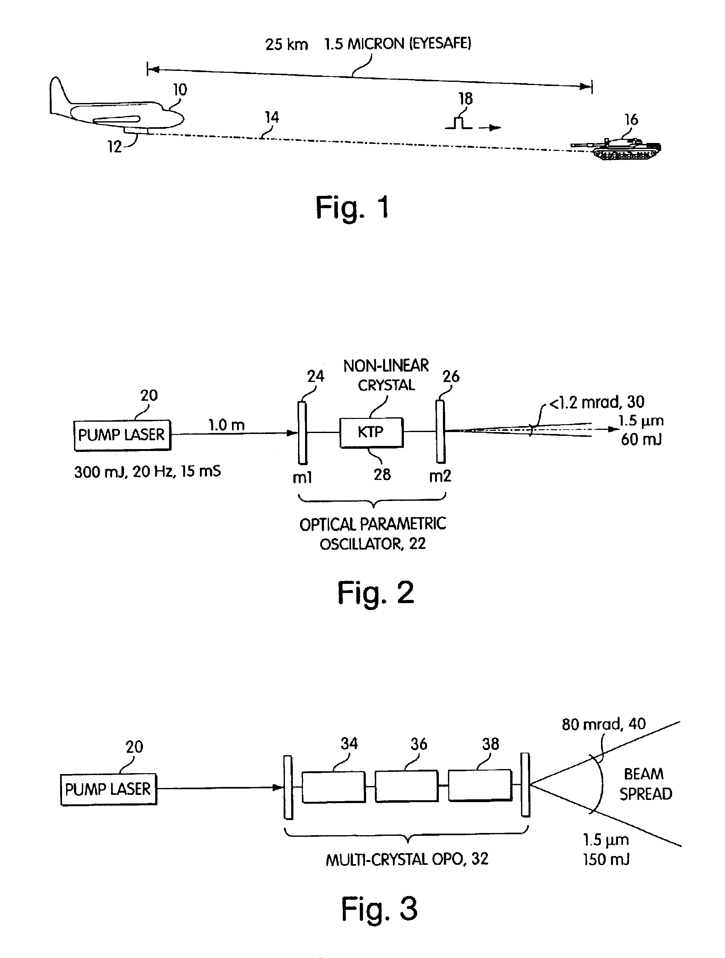
[0028]Referring now to FIG. 1, for eye safe laser target designation or target illumination, in an airborne application an aircraft 10 is provided with a laser target designator 12 which provides a beam 14 directed to a target 16 in which the target is illuminated by a single pulse 18.

[0029]It will be appreciated that it is important to provide an eye safe laser for such laser target designation or illumination due to the fact that human beings may be in the area and if the radiation impinges upon the eye of a human being, damage can occur unless the radiation is in the 1.5 micron range.

[0030]For long distance eye safe laser ranging and illumination, for instance up to and exceeding 25 km, it is only with difficulty that one can provide sufficient power on target to operate at such long ranges.

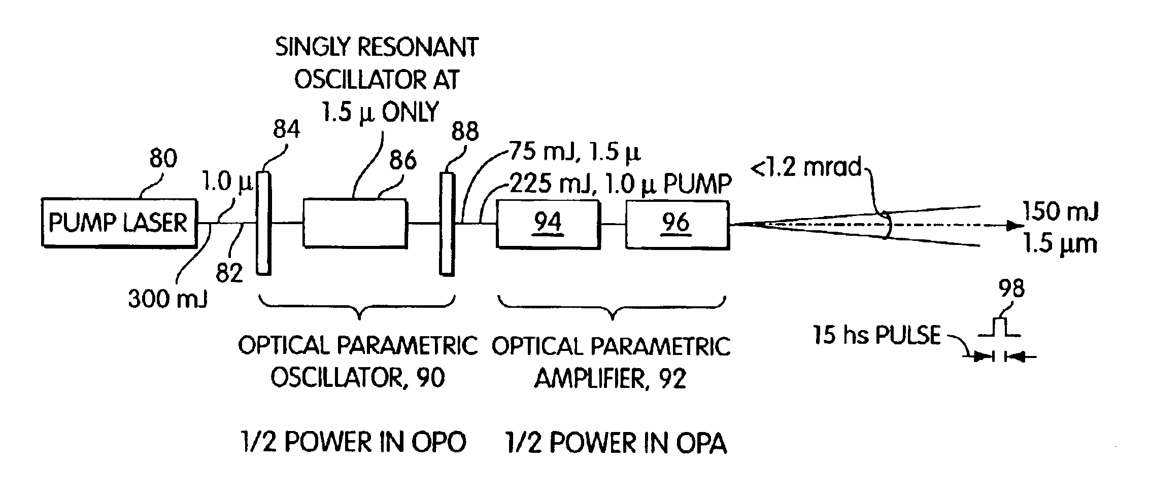
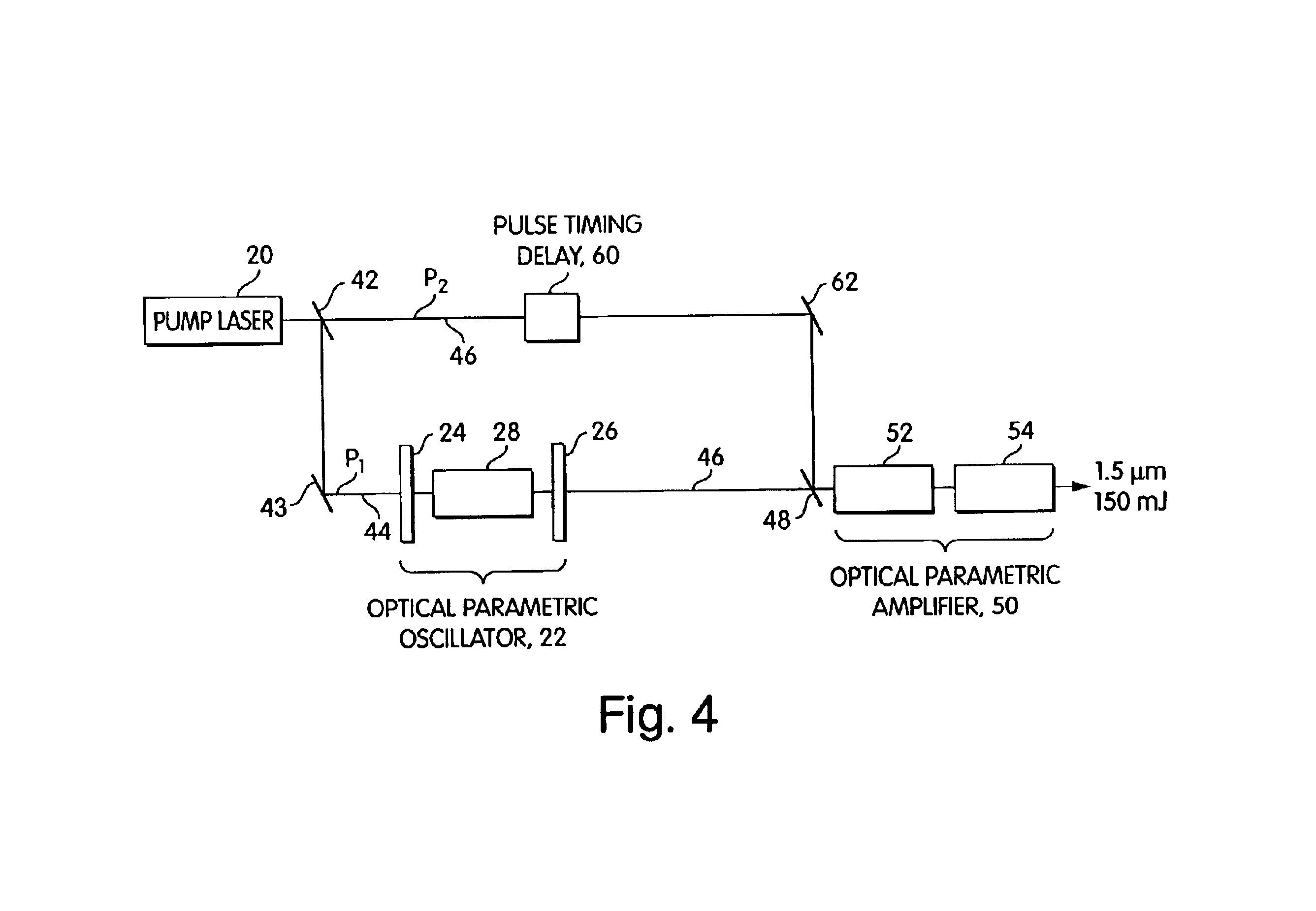
[0031]Referring to FIG. 2, as has been attempted, a pump laser 20 has been utilized to pump an optical parametric oscillator 22 having an input mirror 24 and an output mirror 26 into which is ...


PUM


Abstract

A higher intensity eye safe laser is provided for long range target designation or illumination as well as long range eye safe communications by providing a single beam line combination of an optical parametric oscillator and optical parametric amplifier which are used to double the output of the optical parametric oscillator while limiting beam spread to less than 1.2 milliradians assuming a 20 mm clear aperture. The OPO/OPA combination requires no conditioning, isolation or synchronization optics and provides a factor of two improvements in beam quality as compared to an equivalent optical parametric oscillator, with the subject system providing a compact robust configuration. The high conversion is provided by the use of a simple optical parametric oscillator seeding an optical parametric amplifier without double passing the pump pulse in the optical parametric oscillator. Low beam divergence operation is provided with minimum optics in a compact space with the optical parametric oscillator operating at a reduced signal intercavity flux which provides increased damaged threshold margins.

Description

CROSS REFERENCE TO RELATED APPLICATIONS[0001]This utility patent application relates to U.S. Provisional Application No. 60 / 390,952, entitled: Efficient, High Brightness KTP Optical Oscillator—Amplifier In Single Beamline and filed Jun. 24, 2002.FIELD OF INVENTION[0002]This invention relates to eye safe lasers and more particularly to the utilization of a combined optical parametric oscillator and an optical parametric amplifier to significantly increase power without increasing beam divergence.BACKGROUND OF THE INVENTION[0003]High-energy “eye safe” laser illumination is needed for various ranging and illumination applications most specifically with respect LIDAR and gated viewing systems. Of specific interest is single pulse identification at ranges exceeding 25 km using a 1.5 micron source packaged for airborne operation. The desired combination of high pulse energy, low beam divergence within the system packaging and operating constraints has proved challenging as reported by Lar...

Claims


Application Information

Patent Timeline
IPC IPC(8): H01S3/10G02F1/35
CPCG02F1/39
Inventor MCCARTHY, JOHN C.
Owner GULA CONSULTING LLC
Why Eureka
Try Eureka