Optical telemetry of data and power for wireless biomedical sensors and actuators

a biomedical sensor and actuator technology, applied in the field of optical telemetry of data and power for wireless biomedical sensors and actuators, can solve the problems of inability to determine non-invasive methods, significant potential for infection, and large size or weight of wireless systems

Inactive Publication Date: 2005-05-24
INNERSEA TECH
View PDF7 Cites 86 Cited by
  • Summary
  • Abstract
  • Description
  • Claims
  • Application Information

AI Technical Summary

Benefits of technology

[0011]Therefore it would be advantageous to provide a system for acquiring biomedical information and allowing for transdermal communications that does not involve tethering of the electrodes through wires for either power or signal transmission and that does not require the use of RF systems.

Problems solved by technology

Monitoring of physiological signals for medicine and research presents unique problems that include the acquisition of this information in vivo and the transmission of this information to instruments external to the body where it may be stored and analyzed.
Since many of these physiological signals cannot be determined by non-invasive methods, they must be acquired by the use of implanted sensors, transducers, or electrodes and provided to the external device via transdermal catheters or percutaneous connectors.
Catheters and percutaneous connectors, however, are easily damaged, can create a significant potential for infection, and also may be subject to marsupialization by epithelial downgrowth.
RF systems have several disadvantages, however.
For example, for many implant sites RF wireless systems can be too large or heavy.
A RF system that is too heavy and too dense compared to the surrounding environment may be subject to non-uniform accelerations compared to the physiological structures surrounding it and physically move, damaging or destroying the physiological structures that were to be monitored.
In addition, RF wireless systems are themselves subject to RF interference from telecommunication devices, microwave ovens, computers, cell phones and other common electronic devices.
Research in the field of neuroprosthetics is hampered by the need for wires to access these bioelectric signals from the nervous system and the percutaneous connectors used to bring these signals out of the body.
These wires inadvertently tether, or physically link, the devices to the skull or other fixed structures.
For example, the tethering of the implanted electrodes to the skull by even the finest lead wires may result in non-uniform acceleration of the tethered device due to normal head movement.
This non-uniform acceleration of the implanted device can damage neurons due to the movement of the implanted device relative to the brain within the skull.
This movement of the implanted device relative to the brain can lead to the damage and destruction of nearby neurons that results in a loss of signal, or a decrease in signal strength, and a loss of information.
In addition, the possible long term location drift of the electrodes can result in a lack of stability of the received signals or, as described above, damage or destruction of the adjacent neurons.
In addition, the electrode may move entirely out of the potential gradient in the extracellular space, thereby entirely losing the signal of interest.
In addition, the volume and mass of the batteries themselves would militate against their use in the neural environment due to compression of the surrounding neurons.
RF transmission of power or data also creates substantial electrical interference for implanted devices.
In addition, the use of antennas, although small due to the microwave frequencies involved are relatively large and dense relative to the local neural structures and, in addition, could heat local tissue, resulting in further damage.
To access information from all these electrodes using wire interconnects would result in a wire bundle that would be prohibitively large and stiff, resulting in a large tethering problem.
Multiplexing these thousands of signals into even a few wires would not eliminate the tethering problem.
In this case the density of wires would still be so great that the differential acceleration caused by normal head motion or acceleration encountered while riding in cars, etc., may cause electrode motion resulting in damage and loss of signals.

Method used


Image

  • Optical telemetry of data and power for wireless biomedical sensors and actuators
  • Optical telemetry of data and power for wireless biomedical sensors and actuators
  • Optical telemetry of data and power for wireless biomedical sensors and actuators

Examples


Embodiment Construction

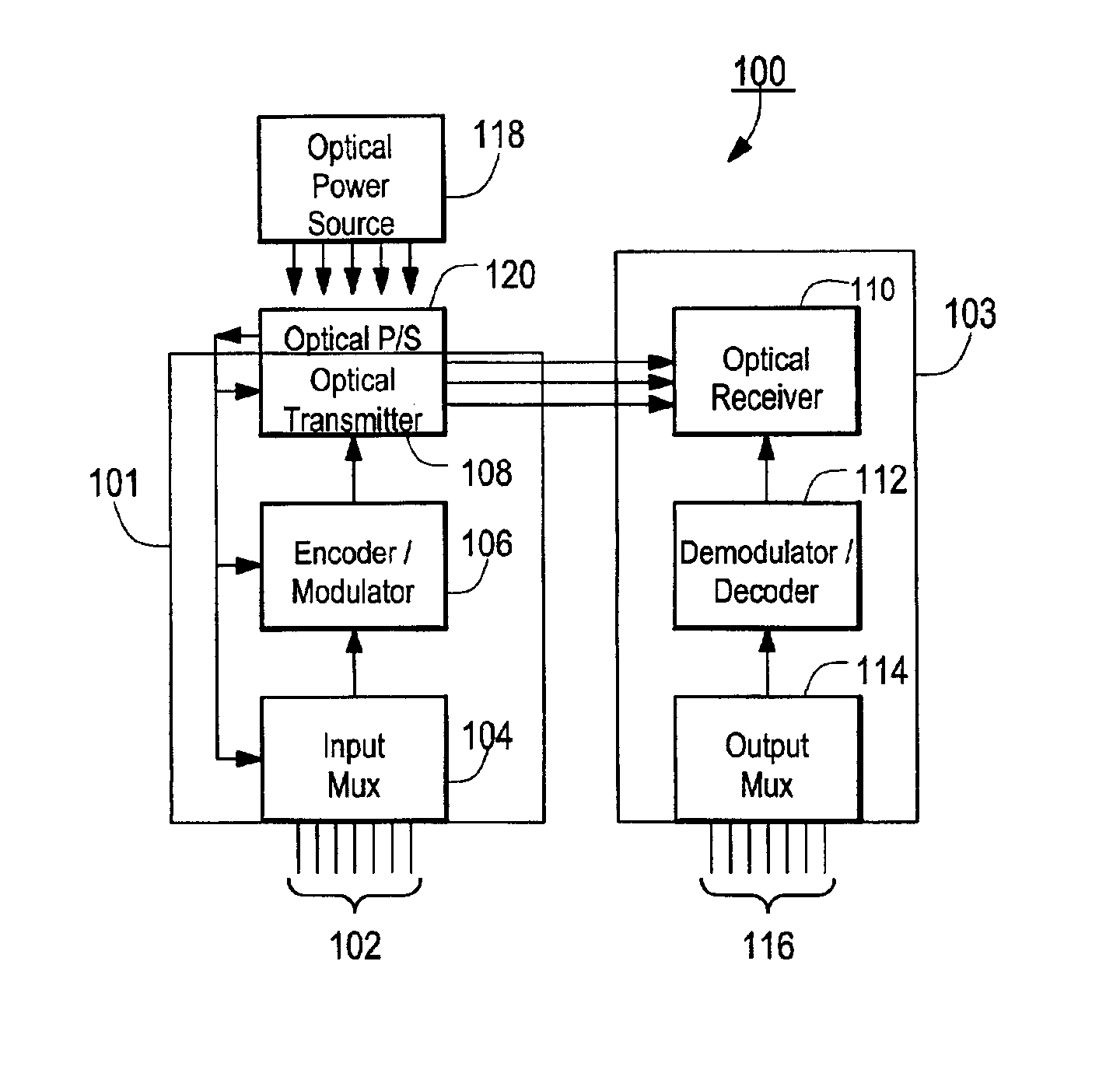
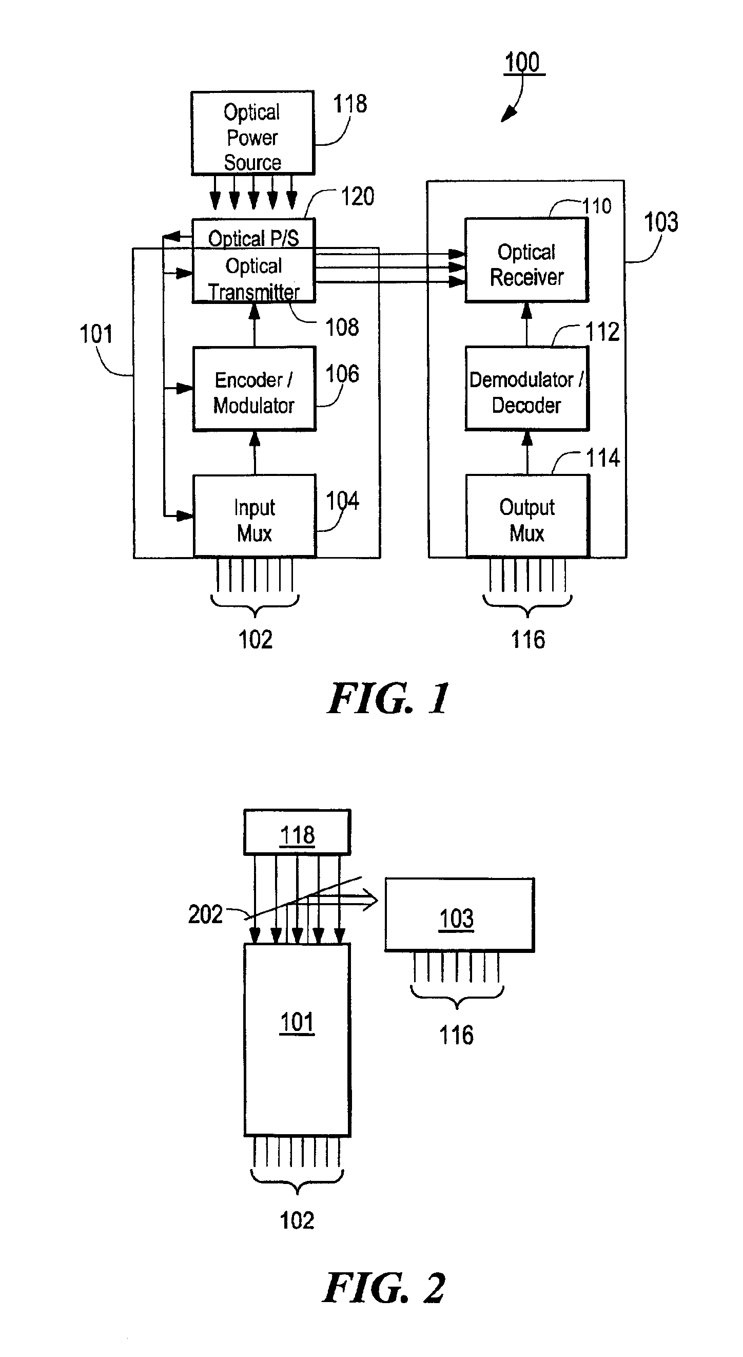
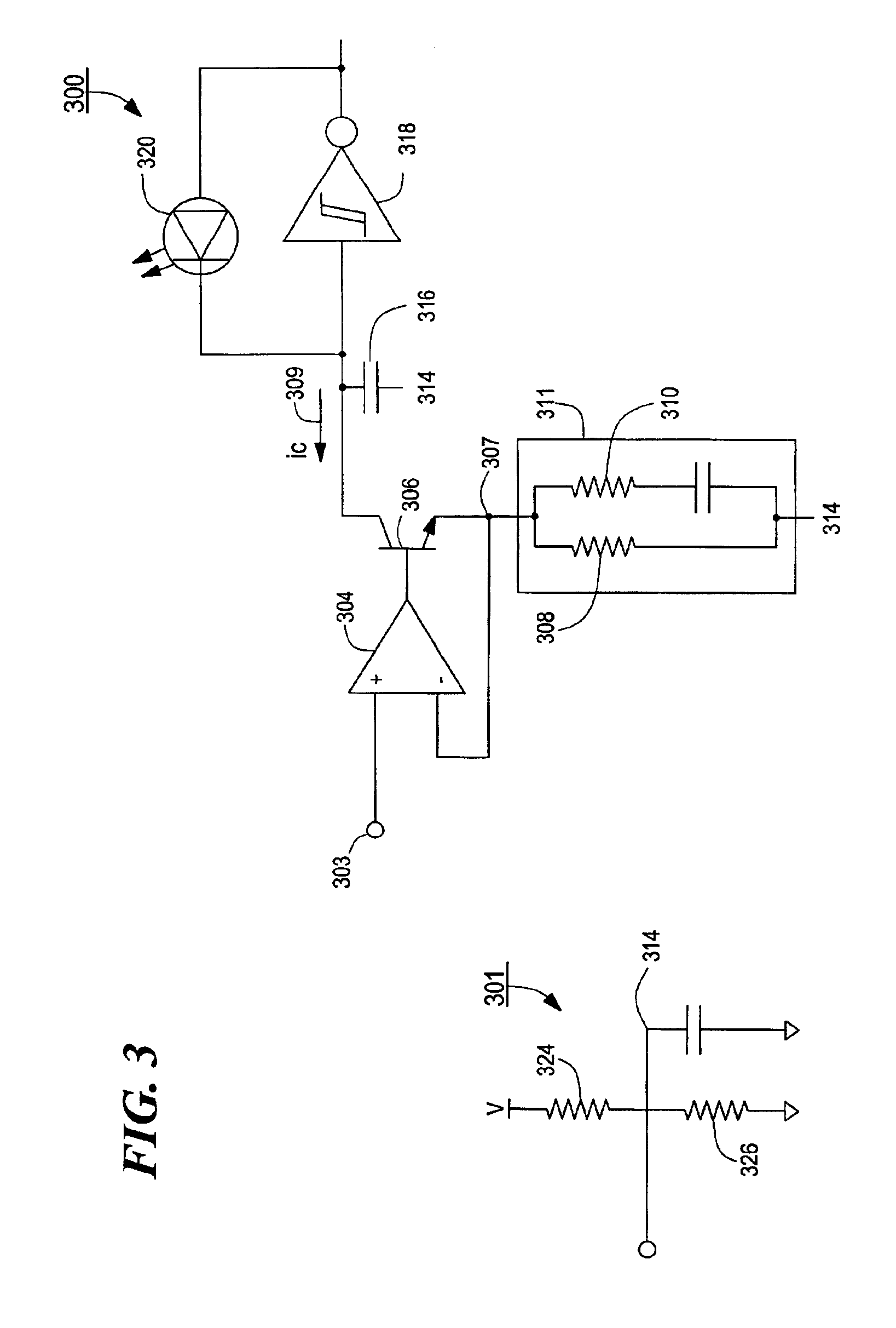
[0025]FIGS. 1 and 2 depict a first embodiment of an apparatus and corresponding method for the optical telemetry of data and power for wireless biomedical sensors and actuators. In particular, FIGS. 1 and 2 depict a unidirectional communications link for providing telemetry data or other operational data from a sensor or other biomedical device implanted within a body cavity. FIGS. 3, 4, and 5 depict particular circuits suitable for performing at least some of the functions illustrated in FIGS. 1 and 2. FIG. 6 is a schematic diagram depicting an optical power supply suitable for providing power to devices implanted in vivo. FIG. 7 depicts another embodiment that provides for bi-directional communications to and from the device or devices implanted within the body cavity, and FIG. 8 depicts a circuit for removing various DC and other low frequency offsets that occur due to the nature of the environment within the body cavity.

[0026]As depicted in FIG. 1, an optical telemeter 100 inclu...


PUM


Abstract

An apparatus and corresponding method for providing data communications to and from a location within a body cavity in which an internal transmitter receives a first data stream from an in vivo sensor, electrode, or transducer. The internal transmitter is configured and arranged to asynchronously modulate the first data stream and to provide as an output a first optical signal carrying the asynchronously modulated first data stream. The apparatus further includes an external receiver that is configured and arranged external to the body cavity such that an optical input to the external receiver is optically coupled to the internal transmitter output and receives the optical signal therefrom. The external receiver asynchronously demodulates the received optical signal and provides as an output at least one signal indicative of the first data stream.

Description

CROSS REFERENCE TO RELATED APPLICATIONS[0001]This application claims priority under 35 U.S.C. §119(e) to provisional patent application Ser. No. 60 / 238,219 filed Oct. 5, 2000, the disclosure of which is incorporated by reference herein.STATEMENT REGARDING FEDERALLY SPONSORED RESEARCH OR DEVELOPMENT[0002]N / ABACKGROUND OF THE INVENTION[0003]Monitoring of physiological signals for medicine and research presents unique problems that include the acquisition of this information in vivo and the transmission of this information to instruments external to the body where it may be stored and analyzed. These physiological signals may include neural waveforms that result from the firing of individual or groups of neurons, electroencephalogram (EEG) signals from the spatial summation of neural signals, electromyogram (EMG) signals that result from the activation of muscle tissue, and electrocardiogram (EKG) signals that result from contractions of the heart. Other physiological variables that ma...

Claims


Application Information

Patent Timeline
Patent Type & Authority Patents(United States)
IPC IPC(8): A61B5/00A61N1/08H04B10/00A61N1/372
CPCA61B5/0017A61N1/08H04B10/807A61B5/0028A61B5/0002Y10S128/903
Inventor EDELL, DAVID J.LARSON, BRUCE C.SEXTON, SEAN V.
Owner INNERSEA TECH
Why Eureka
Try Eureka