Function block implementation of a cause and effect matrix for use in a process safety system

a technology of process safety and function blocks, applied in the field of safety systems, can solve the problems of tedious programming steps, serious injury or even death of plant personnel, hazards in the plant, etc., and achieve the effects of easy integration, easy documenting, testing and debugging, and easy creation

Inactive Publication Date: 2005-05-24
FISHER-ROSEMOUNT SYST INC
View PDF7 Cites 37 Cited by
  • Summary
  • Abstract
  • Description
  • Claims
  • Application Information

AI Technical Summary

Benefits of technology

[0008]The cause and effect function block may include a cause and effect matrix logic or multiplexer coupled to one or more state machines, with a separate state machine existing for each effect output. The multiplexer receives and decodes each of the cause inputs and, based on the cause inputs and a previously identified cause and effect matrix logic, provides a trip signal to one or more of the state machines. Upon receiving a trip signal, a state machine forces an associated effect output into a tripped or safe state. If desired, the state machine may then require one or more other signals, such as reset signals from a user or from the process, to transition between a set of states associated with safely returning the safety system from the tripped or safe state to a normal state (in which the process operates normally). Moreover, each state machine can provide a signal indicating the current state of the state machine as well as a signal indicating the first cause which resulted in the state machine forcing its associated effect signal to the tripped or safe state.
[0009]This cause and effect function block is easy to create, as, in its basic form, it only requires the configuration or safety engineer to supply a cause and effect matrix logic thereto and to specify values for a set of parameters to define the desired operation of the cause and effect function block. This cause and effect function block is also easy to integrate into a controller or logic solver which uses function block logic as the cause and effect function block can be integrated in the same manner as any other function block, by interconnecting inputs and outputs of the cause and effect function block to other function blocks or elements within the control strategy. As a result, this cause and effect function block is also easy to document, test and debug. Moreover, this cause and effect function block may provide additional functionality not normally provided in safety systems, such as enabling the safety system to cycle through a series of states before returning a particular safety device from a tripped or safe state to a normal state of operation.

Problems solved by technology

Furthermore, in many processes, a separate safety system is provided to detect significant safety related problems within the process plant and to automatically close valves, remove power from devices, switch flows within the plant, etc. when a problem occurs which might result in or lead to a serious hazard in the plant, such as a spill of toxic chemicals, an explosion, etc.
While, in the past, configuration or safety engineers have manually translated the cause and effect matrix into the safety system controllers using different programming languages, this programming step unfortunately has been tedious, time consuming and fraught with errors, which can be serious because a failure of the safety system to operate properly can lead to serious injury or even death on the part of plant personnel and to the destruction of potentially millions of dollars of equipment and material within a plant.
Because safety logic translated in such a manner can result in highly complex programs, these programs can still be difficult and time consuming to test and debug and can require a lot of documentation.
Moreover, it is difficult to use these types of programs in a control routine that uses a function block programming strategy to implement control functions.

Method used


Image

  • Function block implementation of a cause and effect matrix for use in a process safety system
  • Function block implementation of a cause and effect matrix for use in a process safety system
  • Function block implementation of a cause and effect matrix for use in a process safety system

Examples


Embodiment Construction

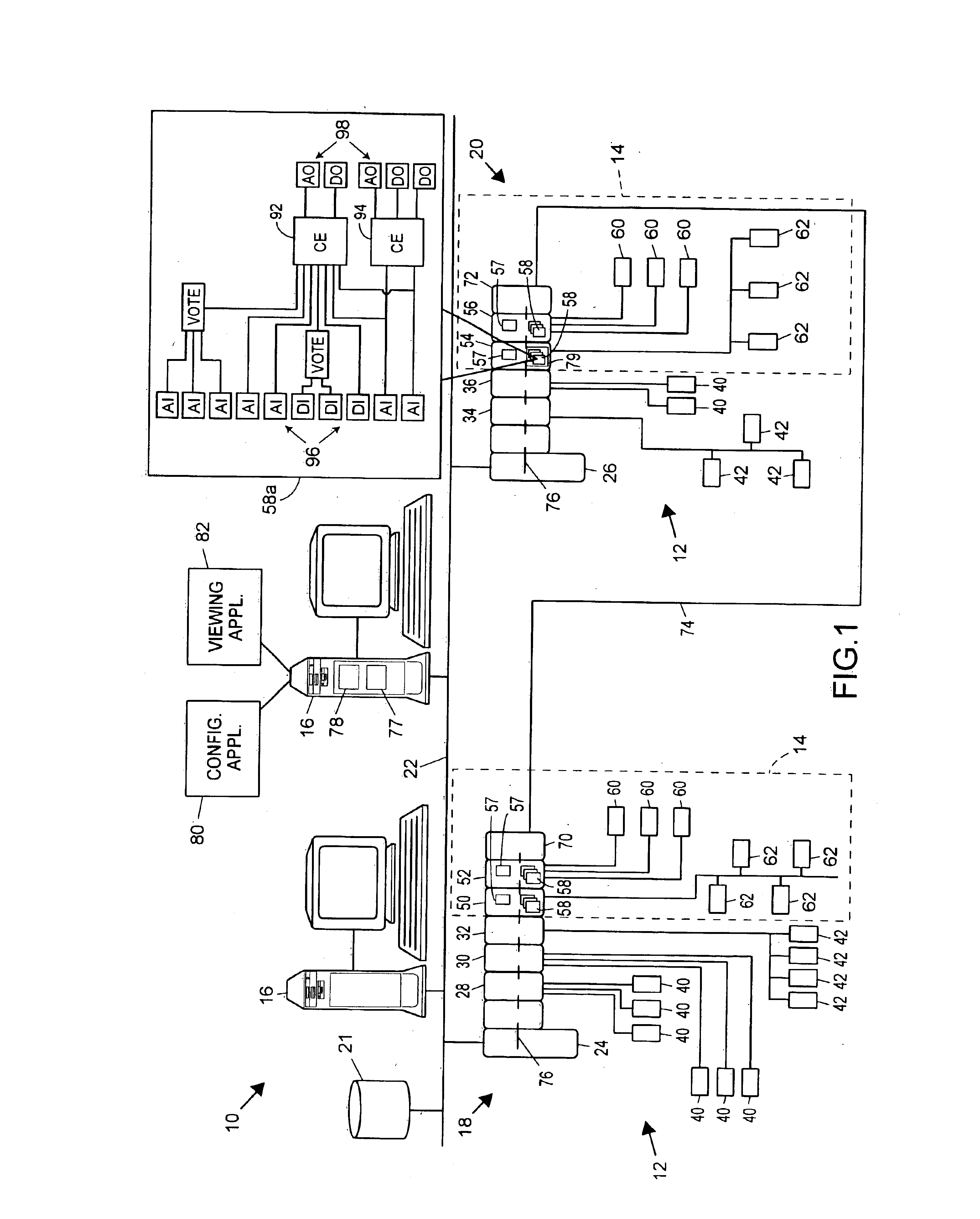
[0014]Referring now to FIG. 1, a process plant 10 includes a process control system 12 integrated with a safety system 14 (indicated by dotted lines), which generally operates as a Safety Instrumented System (SIS) to monitor and override the control provided by the process control system 12 to maximize the likely safe operation of the process plant 10. The process plant 10 also includes one or more host workstations, computers or user interfaces 16 (which may be any type of personal computers, workstations, PDAs, etc.) which are accessible by plant personnel, such as process control operators, maintenance personnel, safety engineers, etc. In the example illustrated in FIG. 1, two user interfaces 16 are shown as being connected to two separate process control / safety control nodes 18 and 20 and to a configuration database 21 via a common communication line or bus 22. The communication network 22 may be implemented using any desired bus-based or non-bus based hardware, using any desire...


PUM


Abstract

A cause and effect function block, which can be easily integrated into a function block diagram programming environment in a process plant safety system to implement the cause and effect logic specified by a traditional cause and effect matrix, includes a set of cause inputs and a set of effect outputs. A multiplexer within the cause and effect function block receives each of the cause inputs and is coupled to one or more state machines, with a separate state machine existing for each effect output. The multiplexer decodes each of the cause inputs and, based on the cause inputs and previously identified cause and effect matrix logic, provides a trip signal to one or more of the state machines. Upon receiving a trip signal, a state machine forces an associated effect output into a tripped or safe state. If desired, the state machine may then use one or more other signals, such as signals from a user or from the process, to transition between a set of different states used to safely return the process plant back to the normal operating state from the tripped or safe state.

Description

FIELD OF TECHNOLOGY[0001]The present invention relates generally to safety systems used in process plants and, more particularly, to a function block implementation of a cause and effect matrix used to control the operation of a safety system used within a process plant.DESCRIPTION OF THE RELATED ART[0002]Process control systems, like those used in chemical, petroleum or other processes, typically include one or more process controllers communicatively coupled to at least one host or operator workstation and to one or more field devices via analog, digital or combined analog / digital buses or lines. The field devices, which may be, for example valves, valve positioners, switches and transmitters (e.g., temperature, pressure and flow rate sensors), perform functions within the process plant such as opening or closing valves and measuring process parameters. The process controllers receive signals indicative of process measurements made by the field devices and / or other information per...

Claims


Application Information

Patent Timeline
Patent Type & Authority Patents(United States)
IPC IPC(8): G05B9/02
CPCG05B9/02
Inventor OTT, MICHAELLAW, GARYSTEVENSON, DENNISHAVEKOST, ROBERTNAIDOO, JULIANSHERRIFF, GODFREY R.
Owner FISHER-ROSEMOUNT SYST INC
Why Eureka
Try Eureka