Method of producing a surface acoustic wave device

a surface acoustic wave and acoustic wave technology, applied in the direction of piezoelectric/electrostrictive transducers, generators/motors, transducers, etc., can solve the problems of insufficient adaptation of devices to high frequency operation, inability to obtain necessary good characteristics, and inability to sufficiently reduce the resistance of idt electrodes, etc., to achieve the effect of preventing idt electrode damage, reducing manufacturing costs, and increasing throughpu

Inactive Publication Date: 2005-05-31
MURATA MFG CO LTD
View PDF12 Cites 6 Cited by
  • Summary
  • Abstract
  • Description
  • Claims
  • Application Information

AI Technical Summary

Benefits of technology

[0014]By forming an interdigital transducer (IDT) electrode, or the IDT electrode and a reflector on a piezoelectric substrate, each of the IDT electrode and the reflector having a multi-layer film structure including at least one layer containing, as a major component, a metal with a specific gravity of at least about 15 and a film-thickness of at least about 10 nm as a high specific gravity metal component containing layer, and at least one layer including as a major component a metal with a specific gravity of up to about 10 and a bulk resistivity, at 20° C., of up to about 10×10−8 Ω·m, and a film-thickness of at least about 10 nm as a low specific gravity metal component containing layer, excellent resonator and filter characteristics can be ensured, and also, frequency dispersion, which may be caused by dispersions in film-thickness, is minimized. Thus, it is unnecessary to perform frequency adjustment, and the manufacturing cost is greatly reduced due to the increased throughput. In addition, damage to the substrate, the IDT electrode, and the reflector is prevented, which further enhances the yield.
[0015]In particular, since the high specific gravity metal component containing layer is provided, an SH wave can be easily excited and reflected. Moreover, since the low specific gravity metal component containing layer is provided, frequency dispersion, which may occur when a plurality of filters and resonators are produced using the same wafer, is minimized. Thus, surface acoustic wave devices having excellent resonance and filter characteristics is obtained.
[0016]In addition, a vibration mode that exerts an undesirable influence over the characteristics is minimized in the film-thickness range in which high excitation and reflection efficiencies can be ensured.

Problems solved by technology

Thus, in some cases, a problem arises in that the necessary good characteristic cannot be obtained.
Moreover, if the film-thicknesses of the IDT electrodes and the reflectors are restricted, it will be more difficult to sufficiently reduce the resistances of the IDT electrodes, and also, problematically, the devices cannot be sufficiently adapted for operation at a high frequency.
However, when these materials are used, it is difficult to obtain filters and resonators having desired characteristics in practice.
However, there is a limit to the reduction in thickness of the IDT electrodes and the reflectors.
Accordingly, a problem arises in that the manufacturing cost is increased due to reduction of throughput, and moreover, the characteristics deteriorate due to damage to the electrodes and the substrates.

Method used


Image

  • Method of producing a surface acoustic wave device
  • Method of producing a surface acoustic wave device
  • Method of producing a surface acoustic wave device

Examples


Embodiment Construction

[0048]The following preferred embodiments will be described for illustration of the characteristics of the present invention.

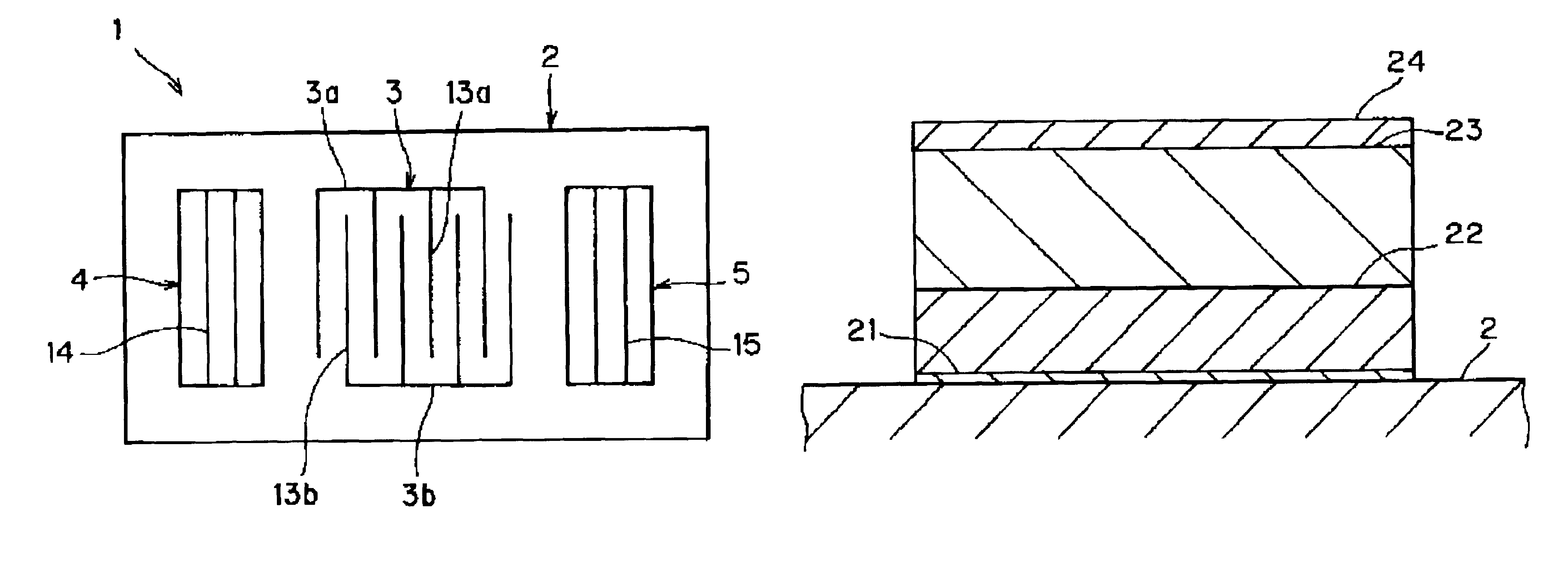
[0049]FIG. 1 is a plan view of a surface acoustic wave device according to a preferred embodiment of the present invention.

[0050]A surface acoustic wave device 1 preferably includes an interdigital transducer (IDT) electrode 3, and reflectors 4 and 5 disposed on both of the sides in the surface acoustic wave propagation direction of the IDT electrode 3 on a piezoelectric substrate 2. The surface acoustic wave device 1 is an end surface reflection-type surface acoustic wave resonator which utilizes an SH wave such as a Love wave or other suitable wave as a surface acoustic wave.

[0051]The IDT electrode 3 preferably includes one pair of interdigital electrodes 3a and 3b having electrode portions 13a and 13b that are interdigitated with each other. The electrode portions 13a and 13b extend substantially perpendicularly to the surface wave propagation direction. Mo...


PUM

PropertyMeasurementUnit
thicknessaaaaaaaaaa
resistivityaaaaaaaaaa
specific gravityaaaaaaaaaa

Abstract

A surface acoustic wave device includes interdigital transducer (IDT) electrode and reflectors disposed on a piezoelectric substrate. Each of the IDT electrode and the reflectors has a multi-layer film structure including at least one layer (high specific gravity metal component containing layer) including as a major component a metal with a specific gravity of at least about 15 and having a film-thickness of at least about 10 nm, and at least one layer (low specific gravity metal component containing layer) including as a major component a metal with a specific gravity of up to about 10 and a volume resistivity as a bulk value (at about 20° C.) of up to about 10×10−8 Ω·m, and having a film-thickness of at least about 10 nm. For example, the multi-layer structure includes an Ni film (low specific gravity metal component containing layer) with a film-thickness of about 150 nm disposed on a Ti film, a Cu film (low specific gravity metal component containing layer) with a film-thickness of about 250 nm disposed on the Ni film, and an Au film (high specific gravity metal component containing layer) with a film-thickness of about 50 nm disposed on the Cu film.

Description

[0001]This application is a Divisional of U.S. patent application Ser. No. 09 / 907,200 filed Jul. 17, 2001, now U.S. Pat. No. 6,545,388.BACKGROUND OF THE INVENTION[0002]1. Field of the Invention[0003]The present invention relates to a surface acoustic wave device for use in, for example, a band-pass filter or a resonator, and the present invention also relates to a method of producing such a surface acoustic wave device.[0004]2. Description of the Related Art[0005]Conventionally, surface acoustic wave devices have been widely used as band-pass filters and resonators. For application of surface acoustic wave devices as band-pass filters, resonators, or other such devices, the most important requirement is that the devices must have good frequency characteristics.[0006]Generally, appropriate materials (electrode materials) for constructing the interdigital transducers (“IDTs”) and reflectors of the surface acoustic wave devices are different from each other, depending on the surface ac...

Claims


Application Information

Patent Timeline
Patent Type & Authority Patents(United States)
IPC IPC(8): H03H9/02H03H9/145H03H3/08H03H9/25
CPCH03H9/14541Y10T29/42Y10T29/49789Y10T29/49128Y10T29/49005Y10T29/49798
Inventor IWAMOTO, TAKASHI
Owner MURATA MFG CO LTD
Why Eureka
Try Eureka