

Method of fabricating a magnetic head device
a magnetic head and head technology, applied in the direction of maintaining the head carrier alignment, recording information storage, instruments, etc., can solve the problems of noise generation, increasing the length of the connecting lead, etc., to suppress the temperature of the head, enhance the cooling effect, and suppress the temperature of the ic chip.
- Summary
- Abstract
- Description
- Claims
- Application Information
AI Technical Summary
Benefits of technology
Problems solved by technology
Method used
Image

Examples
Embodiment Construction
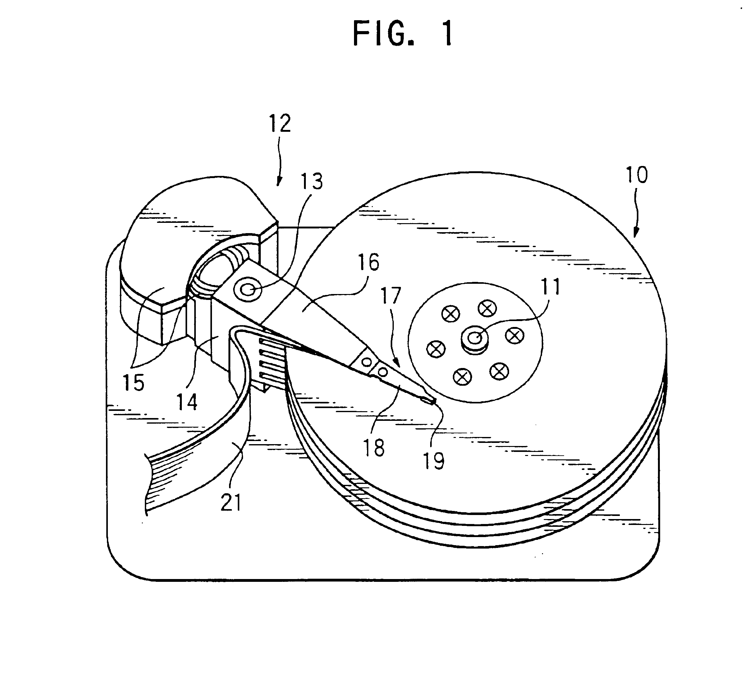
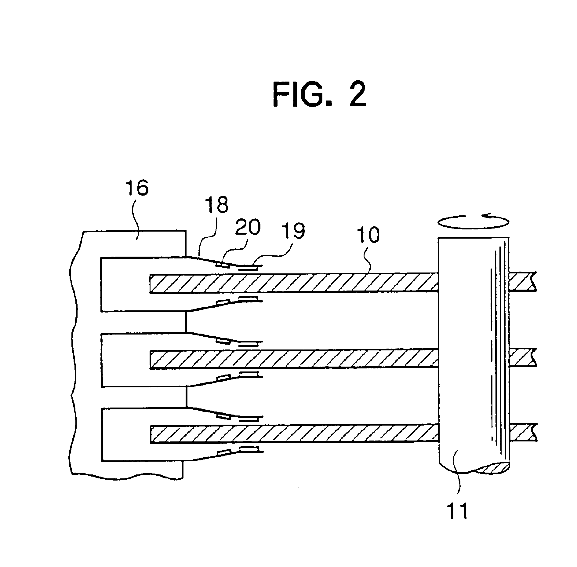
[0047]Referring now to the drawings, particularly to FIG. 1, there is shown in a perspective view a magnetic disc device using a magnetic head device in accordance with one embodiment of the present invention. FIG. 2 shows a carriage assembly used in the magnetic disc device shown in FIG. 1.
[0048]In the arrangement shown in the drawings, it will be understood that a plurality of magnetic recording discs 10 are provided for rotation about an axis of a shaft 11. The magnetic recording discs 10 are rotated by a mechanism which is well known in the art. Adjacent to the magnetic recording discs 10, there is provided a carriage assembly 12 for locating sliders with respect to the discs 10. Each of the sliders has a magnetic head mounted thereon. The carriage assembly 12 primarily comprises a carriage 14 which is rotatable about a shaft 13 and an actuator 15 such as a voice coil motor (VCM) for rotationally driving the carriage 14.
[0049]The carriage 14 supports a plurality of movable arms ...
PUM
| Property | Measurement | Unit |
|---|---|---|
| Mass | aaaaa | aaaaa |
| Length | aaaaa | aaaaa |
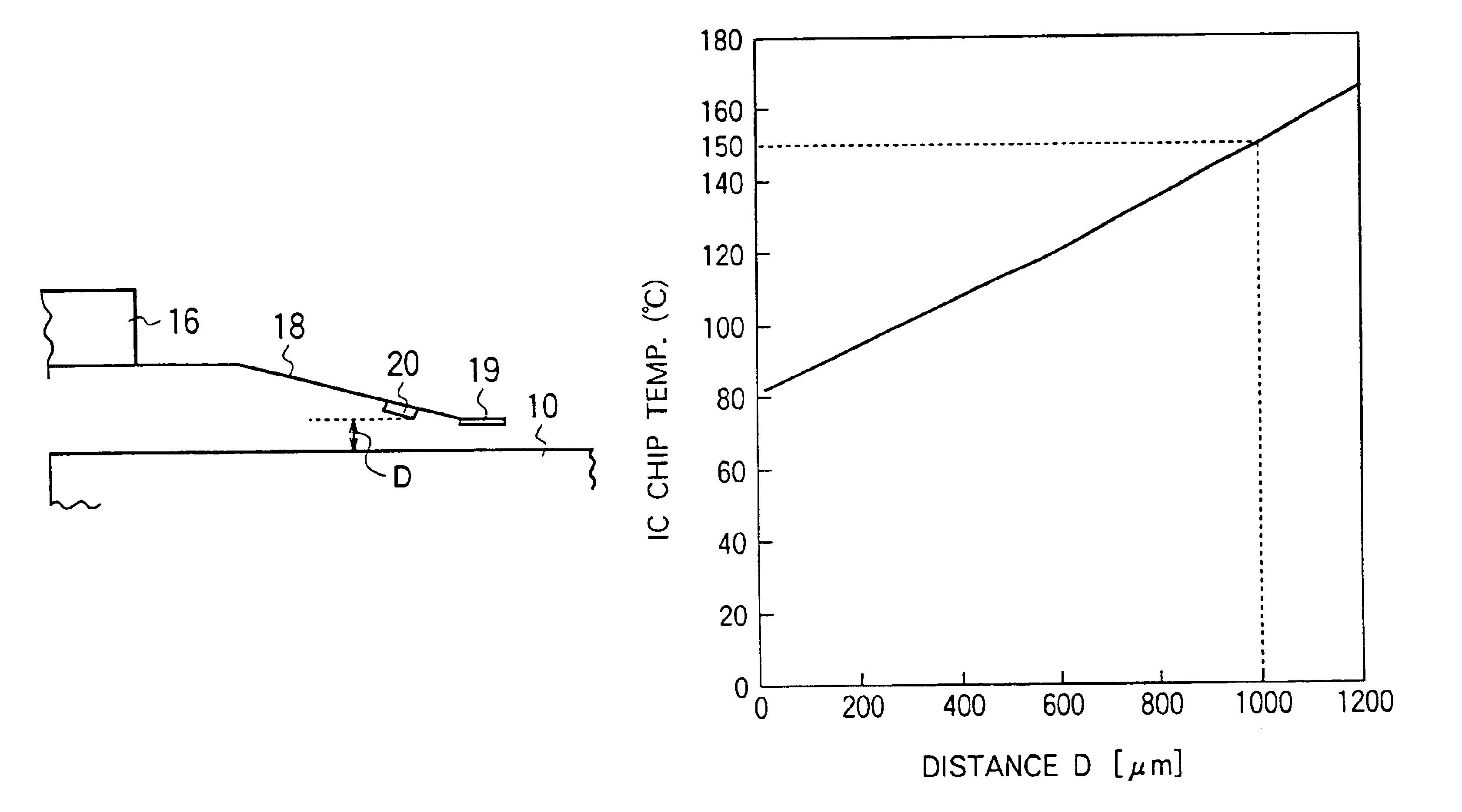
| Distance | aaaaa | aaaaa |
Abstract
Description
Claims
Application Information