
Mobility aid securement for vehicles

a technology for secure vehicles and mobility aids, which is applied in the direction of load securing, transportation and packaging, transportation items, etc., can solve the problems of difficulty in providing the necessary engagement and manual tension to four discrete points of mobility aids, and the occupant of the mobility aid and the operator of the vehicle, and achieves convenient use, convenient use, and convenient use. convenient

Inactive Publication Date: 2005-05-31
SURE LOK INT +1
View PDF30 Cites 34 Cited by
  • Summary
  • Abstract
  • Description
  • Claims
  • Application Information

AI Technical Summary

Benefits of technology

[0008]The invention is a simple-to-use, easily installed power securement system for mobility aids. The system is installed in mass transportation vehicles in such a fashion as to present no obstacle to the traveling public when the system is not in use, but yet is readily available for operation when needed by a mobility aid occupant. The system allows the same space in a vehicle to be used, alternatively, by mobility aid occupants and by ambulatory passengers. The components of the securement system are located in an area of the vehicle which may also be occupied by foldable seats usable by ambulatory passengers. Preferably, these seats may be easily moved away from the area to be occupied by a mobility aid user, and just as easily repositioned for conventional use as desired.
[0010]In use by a mobility aid occupant, the system includes at least one front tensioning assembly having one or more webbed belts provided with one or more hooks to engage the front framework of a mobility aid. A pair of belts is arranged to provide laterally spaced positions for two hooks and belts, thereby ensuring that both the right front and left front portions of a mobility aid will be suitably engaged to restrict both fore, aft, lateral and vertical movement of the front of the mobility aid in relation to the vehicle. One or more rear tensioning assemblies are provided behind the mobility aid station in the vehicle, aft of the front tensioning assembly to permit one or more hooks and belts from a rear tensioning assembly to engage one or more portions of the rear of a mobility aid. Preferably, there are two cooperating rear tensioning assemblies, one located near the inboard part of the mobility aid station and one located near the outboard part of the mobility aid station. These rear tensioning assemblies provide securement of the mobility aid from forward movement as well as from lateral movement.
[0013]The invention thus provides a convenient securement system for a mobility aid passenger utilizing a vehicle having a mobility aid station. The securement system is easily utilized by the mobility aid occupant without the assistance of others, and is likewise convenient to use by a person assisting the mobility aid occupant.
[0014]The mobility aid securement system has a powered tensioning means, thereby permitting appropriate tension to be supplied for securing the mobility aid in position in the vehicle without the need for manually tensioning the securing belts. The system is readily convertible to a stowed configuration, thereby minimizing obstruction or inconvenience to ambulatory passengers. This mobility aid securement system is not subject to being misplaced, soiled or damaged, and does not require complicated installation steps prior to each use.

Problems solved by technology

While numerous methods and devices have been developed for securing wheelchairs and other mobility aids to the interior of vehicles, many of the methods and devices create inconveniences to both the mobility aid occupant and the operator of the vehicle.
In known systems using a plurality of belts and anchors (belts and anchors which are stowed remotely, for example, in a storage locker), such belts and anchors frequently become lost, damaged or soiled when not in use.
Even these systems, however, have an important drawback in that it is difficult to provide the necessary engagement and manual tension to four discrete points on the mobility aid, in the fashion in which the securement apparatus for the mobility aid is usually attached to the vehicle, without the assistance of a person other than the mobility aid occupant.

Method used


Image

  • Mobility aid securement for vehicles
  • Mobility aid securement for vehicles
  • Mobility aid securement for vehicles

Examples


Embodiment Construction

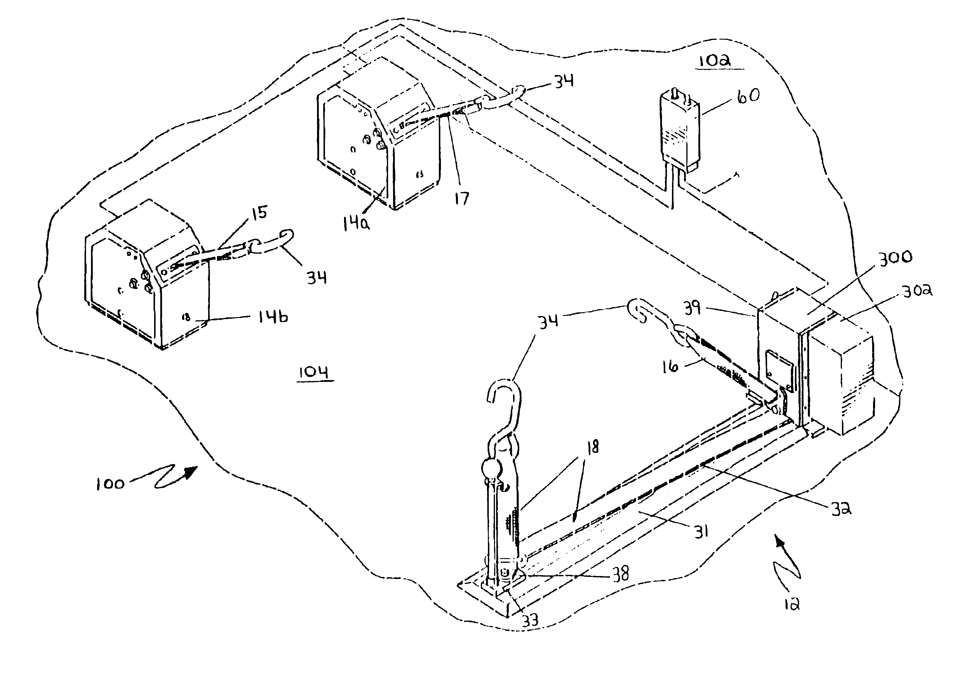
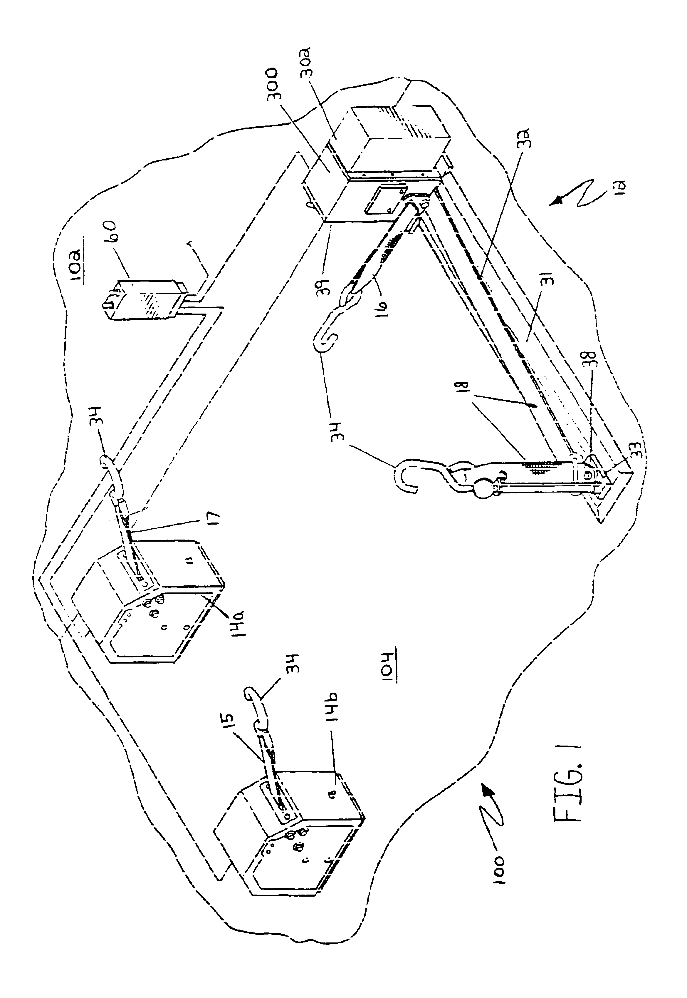
[0039]With reference first to FIG. 1, a mobility aid station 100 is provided in a vehicle having a floor 104 and one or more side walls 102. The station 100 is typically located adjacent one or more seat assemblies (not shown), including seat assemblies having fold-up benches, which can be positioned for conventional seating if desired. A control console 60 is provided for providing signals and power to tension the front tensioning assembly 12 and rear tensioning assemblies 14a and 14b. The console 60 is preferably mounted to be convenient for operation by a mobility aid user or the vehicle operator.

[0040]The front tensioning assembly 12 is depicted in FIG. 1 and utilizes a belt guide 38 that cooperates with a roller-equipped carriage 33 which, in turn, is fitted to a track 31 mounted in or on the floor 104 of the vehicle. The carriage 33 rides within a channel 32 in the track, permitting the belt guide 38 to be positioned transversely at any position along the length of track 31, a...


PUM


Abstract

The invention is an apparatus for securing a mobility aid to the interior of a motor vehicle, such as a bus. The invention includes one or more retractors typically positioned forward of the mobility aid, and one or more retractors typically positioned behind the mobility aid. Some or all of the retractors are provided with a powered tension apparatus for providing opposed tension to the front and rear of the mobility aid, securing it from movement in the vehicle. The tensioning system is capable of being remotely controlled, enabling the securement and release of the mobility aid to be performed easily by either the mobility aid occupant or an operator in the motor vehicle.

Description

RELATED APPLICATION[0001]This application is related to, and claims the benefit of priority from, U.S. Provisional Patent Application Ser. No. 60 / 332,166, filed Nov. 14, 2001.[0002]This invention was made with government support under Grant No. R-42-HD34290 awarded by the Department of Health and Human Services. The government has certain rights in the invention.FIELD OF THE INVENTION[0003]This invention relates to devices for securing a wheelchair or other mobility aid to a vehicle. In particular, the invention includes a system utilizing webbed belts and a power system for providing tension on said belts.BACKGROUND[0004]Over the last two decades, it has become commonplace to accommodate wheelchair users in mass transit vehicles, such as buses, trains or airplanes. Such accommodations typically allow these persons to ride in the vehicle while remaining in a wheelchair or similar mobility aid, such as a powered scooter. It is desirable, under these circumstances, to secure the wheel...

Claims


Application Information

Patent Timeline
IPC IPC(8): A61G3/00A61G3/08B60P3/079B60P3/06
CPCA61G3/0808B60P3/079
Inventor CARDONA, EDGARDOTAKACS, JR., JOSEPHADAMS, THOMAS C.REGER, STEPHEN I.
Owner SURE LOK INT
Learn More