Method and device for separating ion mass, and ion doping device

a technology of ion doping device and separation method, which is applied in the direction of separation process, mass spectrometer, vacuum evaporation coating, etc., can solve the problem of imparting extra thermal load to the substrate, and achieve the effect of preventing extra thermal load and improving operation efficiency

Inactive Publication Date: 2005-05-31
IHI CORP
View PDF7 Cites 7 Cited by
  • Summary
  • Abstract
  • Description
  • Claims
  • Application Information

AI Technical Summary

Benefits of technology

[0010]Arranged outside of an ion deflection casing with a curved contour and having an inlet and an outlet is a hollow exciting current pathway in the form of conductor means which is composed of a widthwise spiral formation running through the inlet and outlet and along the curved contour; an ion beam introduced between the conductors at the inlet is bent in the ion deflection casing for ion mass separation so that a magnetic field which is uniform widthwise can be formed even if the ion deflection casing is of a shape broader in width. As a result, the ion beam broader in width can be bent uniformly widthwise, resulting in obtaining the high-quality ion beam which is broader in width and uniformly ion mass separated.
[0011]Moreover, ion doping can be effected by such high-quality ion beam uniformly ion mass separated and having no extra ion species so that implantation depth distribution of ions can be made uniform and extra thermal load is prevented from being imparted to a substrate. The ion beam broader in width enables ion doping to be effected over an extensive area of a substrate in a single operation, thereby substantially improving operation efficiency.

Problems solved by technology

Such existence of the ion species other than the desired ones will lead to a problem of nonuniformity in implantation depth distribution of P and B through ion doping as well as a problem of imparting extra thermal load to a substrate.

Method used


Image

  • Method and device for separating ion mass, and ion doping device
  • Method and device for separating ion mass, and ion doping device
  • Method and device for separating ion mass, and ion doping device

Examples


Embodiment Construction

[0020]Preferred embodiments of the invention will be described in conjunction with drawings.

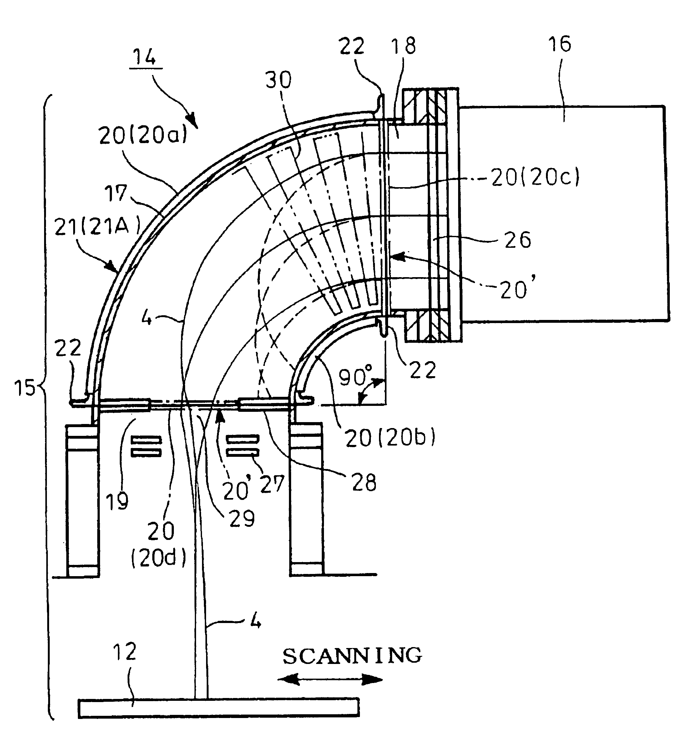
[0021]FIG. 4 is a schematic view showing an ion mass separator 14 and an ion doping apparatus 15 using the same according to the invention in which reference numeral 16 denotes an ion generator with a plasma generating portion; and 17, an ion deflection casing.

[0022]The ion deflection casing 17 shown in FIG. 4 has a substantially fan-shaped side contour to provide a broader space which is long in a direction perpendicular to plane of the drawing. The substantially fan-shaped contour has linear end portions which provide an inlet 18 and an outlet 19, the inlet 18 being connected to the ion generator 16. The inlet 18 and the outlet 19 are angularly displaced with each other by, for example, 90° for deflection of the ion beam 4 with the greater angle.

[0023]Conductor means 20 is arranged outside of the ion deflection casing 17 and is composed of a spiral formation of components mutually spaced ap...


PUM

PropertyMeasurementUnit
sizeaaaaaaaaaa
angleaaaaaaaaaa
magnetic fieldaaaaaaaaaa

Abstract

A hollow exciting current pathway in the form of a conductor is arranged outside of an ion deflection casing with a curved contour and having an inlet and an outlet. The conductor is composed of a widthwise spiral formation of conductors running through the inlet and outlet and along the curved contour with a result that a magnetic field which is uniform widthwise is formed in the ion deflection casing. An ion beam is introduced through between the conductors at the inlet into the hollow exciting current pathway. By the action of the magnetic field through the hollow exciting current pathway, the ion beam is bent depending upon mass of ions. The ion beam with desired mass is taken out through between the conductors at the outlet with a result that an ion beam greater in size can be ion mass separated uniformly.

Description

TECHNICAL FIELD[0001]The present invention relates to an ion mass separation process, an ion mass separator and an ion doping apparatus, enabling stable mass separation in an ion beam larger in size and particularly broader in width.BACKGROUND ART[0002]Ion doping or implanting apparatuses have been used for adding electroactive elements to a semiconductor or adding atoms of an additive to a substrate for adhesive joining of hardly adhesive material to the substrate.[0003]Up to the present, however, there have been no ion mass separating, ion doping apparatus using an ion beam larger in size (for example, 300 mm×800 mm). Conventionally employed in ion doping apparatuses is a non-mass-separation system using an ion beam for ion doping without ion mass separation or a magnetic filter system using a magnetic filter for simple reduction in ratio of lighter ion species (for example, hydrogen ions) in a plasma generating portion of an ion generator.[0004]For example, in an ion doping appar...

Claims


Application Information

Patent Timeline
Patent Type & Authority Patents(United States)
IPC IPC(8): H01J49/26H01J37/04H01J49/32H01J37/05H01J37/317C23C14/48H01L21/265
CPCH01J37/05H01J49/32H01J49/26H01J37/3171H01L21/265
Inventor KUWABARA, HAJIME
Owner IHI CORP
Why Eureka
Try Eureka