Electrostatic microactuator method of activating the same, and camera module
- Summary
- Abstract
- Description
- Claims
- Application Information
AI Technical Summary
Benefits of technology
Problems solved by technology
Method used
Image

Examples
first embodiment
[0062](First Embodiment)
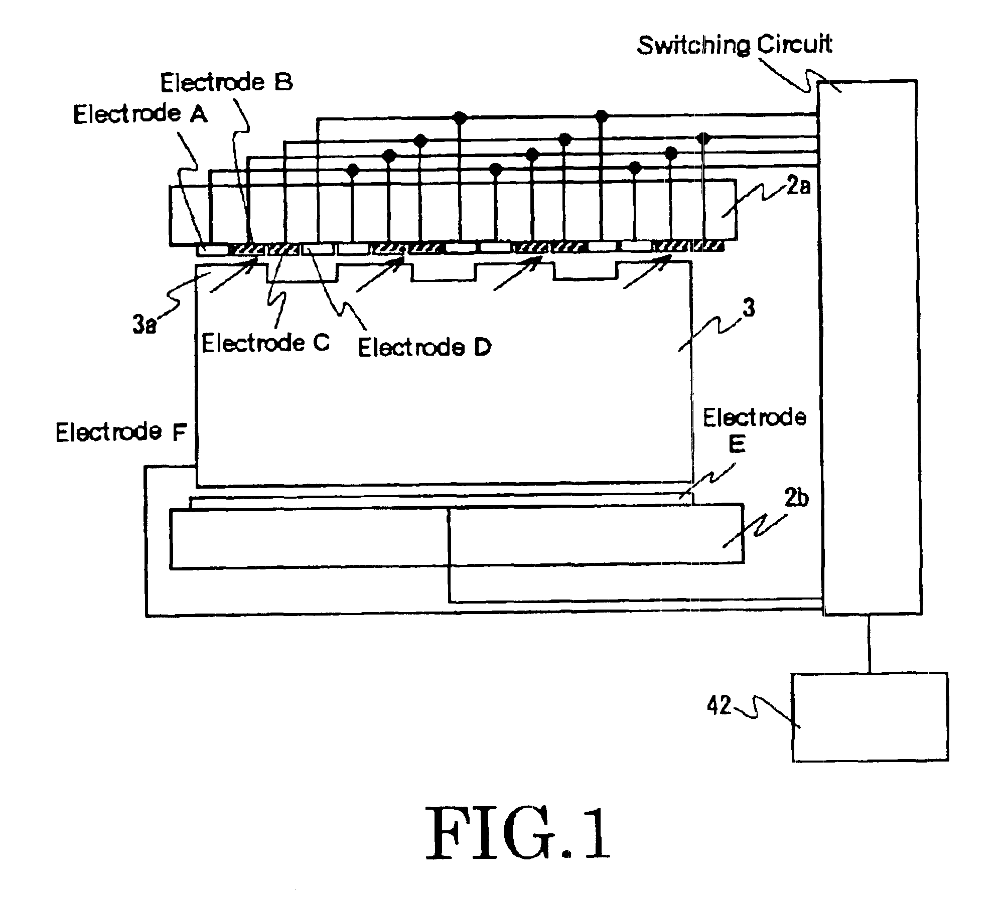
[0063]FIG. 1 is a schematic diagram showing a structure of an exemplary embodiment of an electrostatic actuator according to the present invention. Like reference numerals as used in FIGS. 24 and 25 denote corresponding components in FIG. 1.
[0064]The exemplary electrostatic actuator is comprised of first and second statical members 2a and 2b opposed to each other and a movable piece 3 positioned between them and slidable in a direction designated by an arrow 24.
[0065]The first and second statical members 2a and 2b may be plate-like in shape, or alternatively be semi-cylindrical. When the first and second statical members 2a and 2b have a plate-like shape, the movable piece 3 may accordingly be shaped like a solid or hollow block which has its opposite almost flat surfaces faced with the statical members, or when the first and second statical members 2a and 2b have a semi-cylindrical shape, the movable piece 3 may correspondingly be shaped like a solid or holl...
second embodiment
[0085](Second Embodiment)
[0086]A second embodiment of the electrostatic actuator will now be described in the context of an improved feature of adjusting a balance of voltage applied to the activating electrodes and the lower electrode.
[0087]The inventors reviewed the first embodiment of the electrostatic actuator and obtained some quantitative observations on the clearances between the statical member 2a and the movable piece 3 and the voltage applied to the electrodes.
[0088]A mechanical structure will be outlined for comprehensive recognitions of this embodiment.
[0089]FIG. 6 is a sectional view showing the mechanical structure of the electrostatic actuator of the embodiment of the present invention. The activating electrodes A to D and the lower electrode E have their respective operation surfaces covered with protective film 4, respectively. The protective film 4 is of insulating material such as inorganic composites including silicon oxide and silicon nitride, and organic compos...
third embodiment
[0114](Third Embodiment)
[0115]A third embodiment of the present invention will be described, which is an electrostatic actuator having a well-balanced electrode area of the activating electrodes relative to the lower electrode.
[0116]In this embodiment, instead of adjusting voltage applied to each of the electrodes as described regarding the second embodiment, areas of the upper and lower electrodes are regulated relative to each other to keep the well-balanced state of the attractive force between those electrodes.
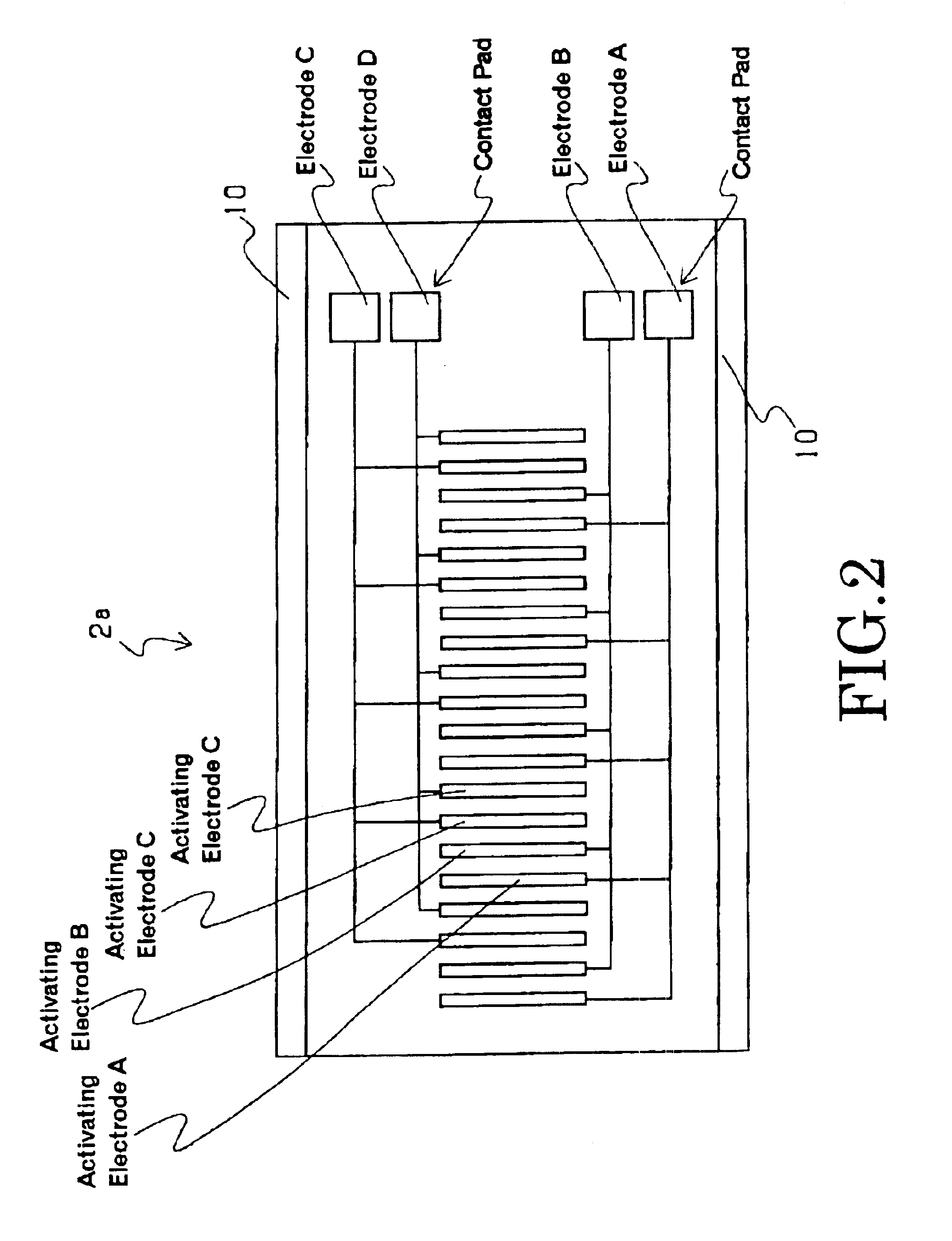
[0117]For example, the activating electrodes A to D are deployed in repeated stripes as shown in FIG. 2, and voltage is applied to a specific group(s) of the electrodes. In response to this, the lower electrode E develops attractive force.
[0118]As to the operation sequence illustrated in FIG. 3, only one group of the same branch electrodes A, B, C or D are supplied with voltage simultaneous with an application of voltage to the lower electrode E. Thus, a face-to-face area ...
PUM
 Abstract
Description
Claims
Application Information
 - R&D
- Intellectual Property
- Life Sciences
- Materials
- Tech Scout
- Unparalleled Data Quality
- Higher Quality Content
- 60% Fewer Hallucinations
Browse by: Latest US Patents, China's latest patents, Technical Efficacy Thesaurus, Application Domain, Technology Topic, Popular Technical Reports.
© 2025 PatSnap. All rights reserved.Legal|Privacy policy|Modern Slavery Act Transparency Statement|Sitemap|About US| Contact US: help@patsnap.com