Systems and methods for wireless telecommunications

a wireless telecommunications and wireless technology, applied in the field of wireless telecommunications systems, can solve the problems of reducing receiver sensitivity, generating internal spurious inter-modulation products, and causing radio frequency problems that are often encountered, so as to reduce the possibility of receiver-side degradation and increase antenna isolation

Inactive Publication Date: 2005-05-31
PULVER FRED
View PDF6 Cites 22 Cited by
  • Summary
  • Abstract
  • Description
  • Claims
  • Application Information

AI Technical Summary

Benefits of technology

[0011]The present invention provides improved systems and methods for providing for the possibility of co-locating separate antennas or antennas organized in an antenna array. Using a unique antenna configuration, the present

Problems solved by technology

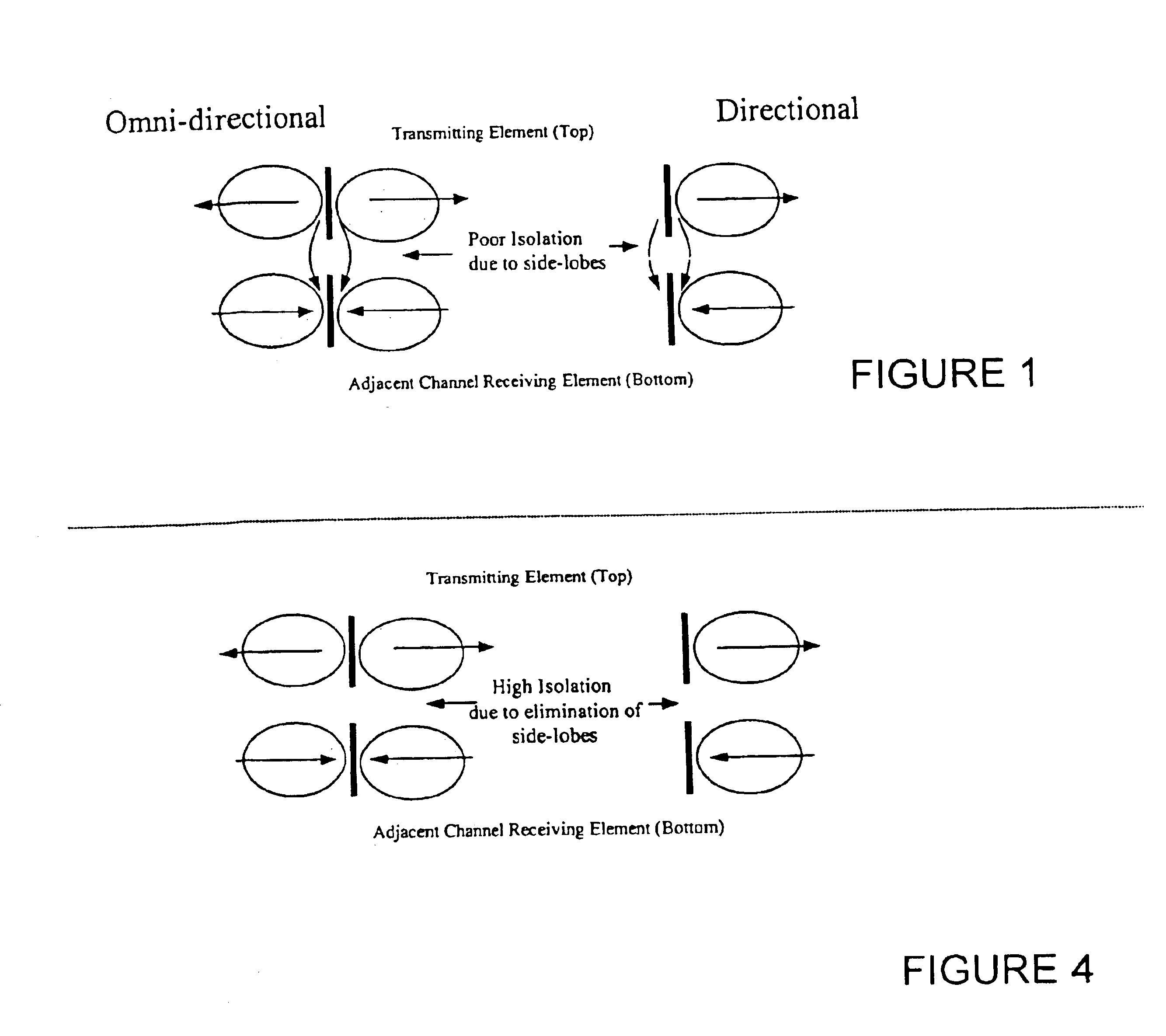
It is know that when attempting to co-locate multiple antennas, such a cellular telephone antennas, radio frequency problems are often encountered.
For example, receiver sensitivity may be degraded due to a transmission signal from an adjacent transmitting antenna migrating into a nearby receiving antenna, and thereby causing internal spurious inter-modulation products to be generated.
When a nearby transmitting signal migrates into another transmitting signal, “backward modulation” products can be retransmitted and can cause interference to reception of weaker signals on the same frequency.
Additional problems impacting receiver sensitivity arise when the broadband noise of a transmitting signal falls within the pass band of a nearby receiver, or when the ultimate selectivity of a receiver is degraded by the reception of a nearby transmitting antenna.
Another problem that exists is the inability to reuse frequencies in a typical wireless local area network such as one in accordance with IEEE 802.11 specifications.
Conditions may not always be conducive for degradation to occur.
However, as the number of co-lo

Method used


Image

  • Systems and methods for wireless telecommunications
  • Systems and methods for wireless telecommunications
  • Systems and methods for wireless telecommunications

Examples


Embodiment Construction

[0031]Before one or more embodiments of the invention are described in detail, one skilled in the art will appreciate that the invention is not limited in its application to the details of construction, the arrangements of components, and the arrangement of steps set forth in the following detailed description or illustrated in the drawings. The invention is capable of other embodiments and of being practiced or being carried out in various ways. Also, it is to be understood that the phraseology and terminology used herein is for the purpose of description and should not be regarded as limiting.

[0032]Embodiments of systems and methods related to wireless telecommunications are described in this detailed description of the invention. For purposes of explanation, numerous specific details are set forth to provide a thorough understanding of embodiments of the present invention. One skilled in the art will appreciate, however, that embodiments of the present invention may be practiced ...


PUM


Abstract

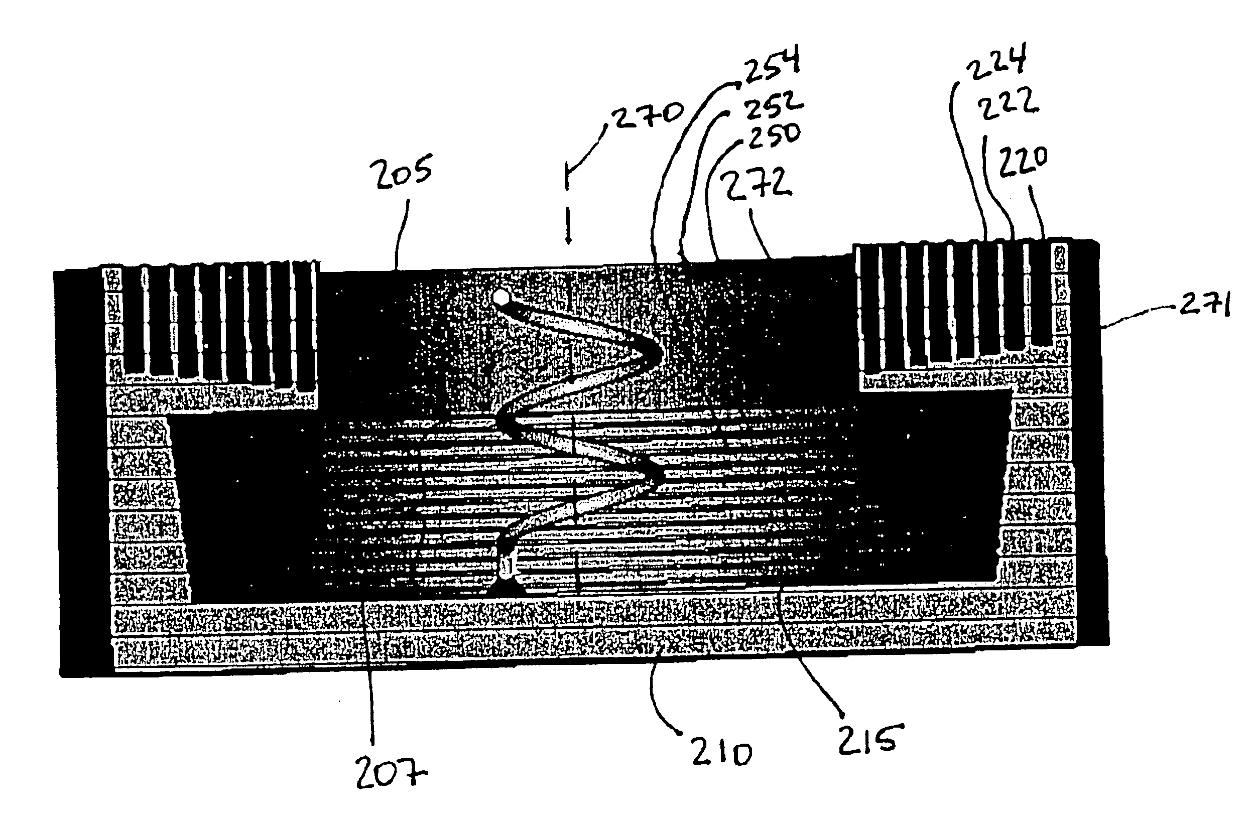
An antenna having an antenna cup and a helical element mounted in the antenna cup. The antenna cup has a side wall extending from a base thereof towards an open end thereof, the side wall having a plurality of slots formed therein, a first set of the slots being arranged parallel to a longitudinal axis of the helical element and a second set of the slots being arranged perpendicular to the longitudinal axis of the helical element, the first set of slots being arranged to surround an upper portion of the helical element and the second set of slots being arranged to surround a lower portion of the helical element. The slots present a high impedance wall to surface currents and thereby significantly reduce side lobe radiation. Such an antenna is particular useful in antenna co-location applications, such as cellular telephone and Wi-Fi applications.

Description

[0001]This application claims the benefit of U.S. Provisional Application No. 60 / 434,411, filed Dec. 19, 2002, which is herein incorporated by reference in its entirety.BACKGROUND[0002]1. Field of the Invention[0003]Embodiments of the present invention relate to telecommunications systems. More particularly, embodiments of the present invention relate to systems and methods for wireless telecommunications.[0004]2. Background of the Invention[0005]It is know that when attempting to co-locate multiple antennas, such a cellular telephone antennas, radio frequency problems are often encountered. For example, receiver sensitivity may be degraded due to a transmission signal from an adjacent transmitting antenna migrating into a nearby receiving antenna, and thereby causing internal spurious inter-modulation products to be generated. When a nearby transmitting signal migrates into another transmitting signal, “backward modulation” products can be retransmitted and can cause interference t...

Claims


Application Information

Patent Timeline
IPC IPC(8): H01Q1/36H01Q1/42H01Q21/00H01Q11/08H01Q13/02H01Q13/06H01Q19/10
CPCH01Q1/362H01Q11/08H01Q19/10H01Q13/0266H01Q13/065H01Q13/0208
Inventor PULVER, FRED
Owner PULVER FRED
Why Eureka
Try Eureka