
Trace flexure suspension with differential insulator and trace structures for locally tailoring impedance

a technology of differential insulator and trace structure, which is applied in the direction of integrated arm assemblies, special recording techniques, instruments, etc., can solve the problems of impedance control, same thickness of insulative layer at the read circuit conductor as at the write circuit conductor, and consequent unwanted degradation of signal integrity

Inactive Publication Date: 2005-05-31
MAGNECOMP
View PDF6 Cites 90 Cited by
  • Summary
  • Abstract
  • Description
  • Claims
  • Application Information

AI Technical Summary

Benefits of technology

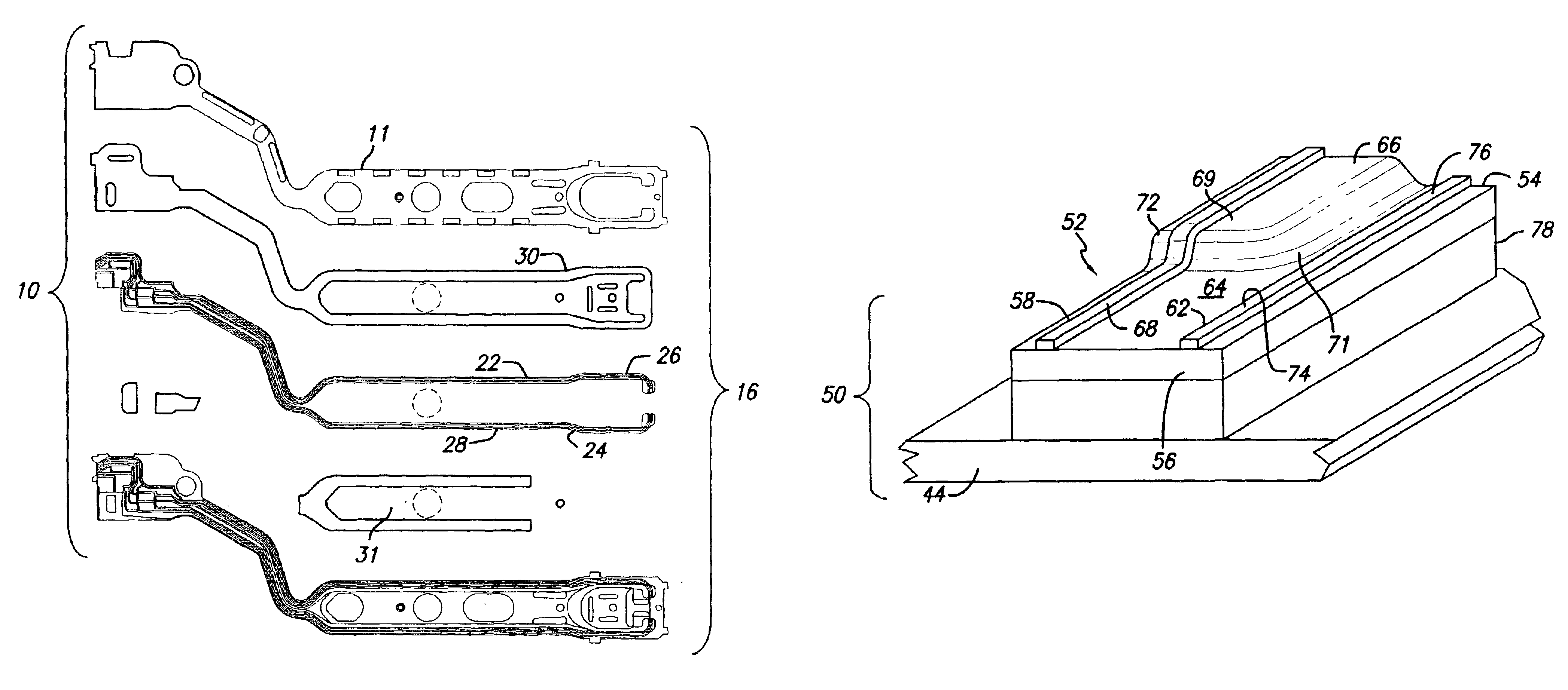
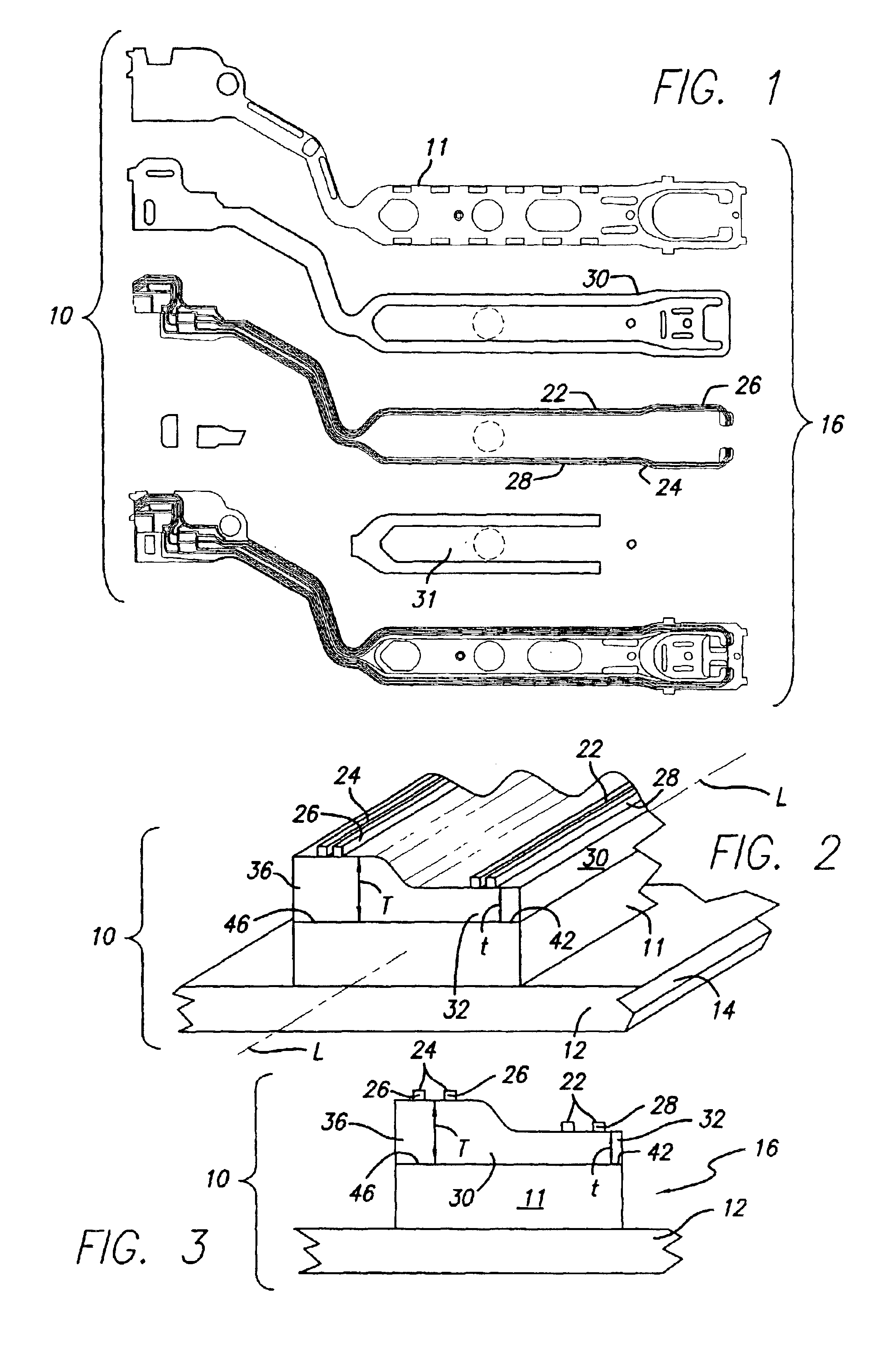
[0010]It is an object of the invention, therefore, to provide greater control of impedance values in a disk drive suspension. It is a further object to provide a more uniform impedance through locally modifying the insulative layer-trace conductor assembly to counteract impedance changing factors, or a local differential in impedance where that is wanted in the circuits of a disk drive suspension. It is a further object to provide a variable thickness in the insulative layer, a variable thickness and width in the trace conductors, separately and combined for maximum versatility in suspension and electrical interconnect design and improved signal integrity. A further object is to provide novel forms of electrical interconnect and flexure for a disk drive suspension.
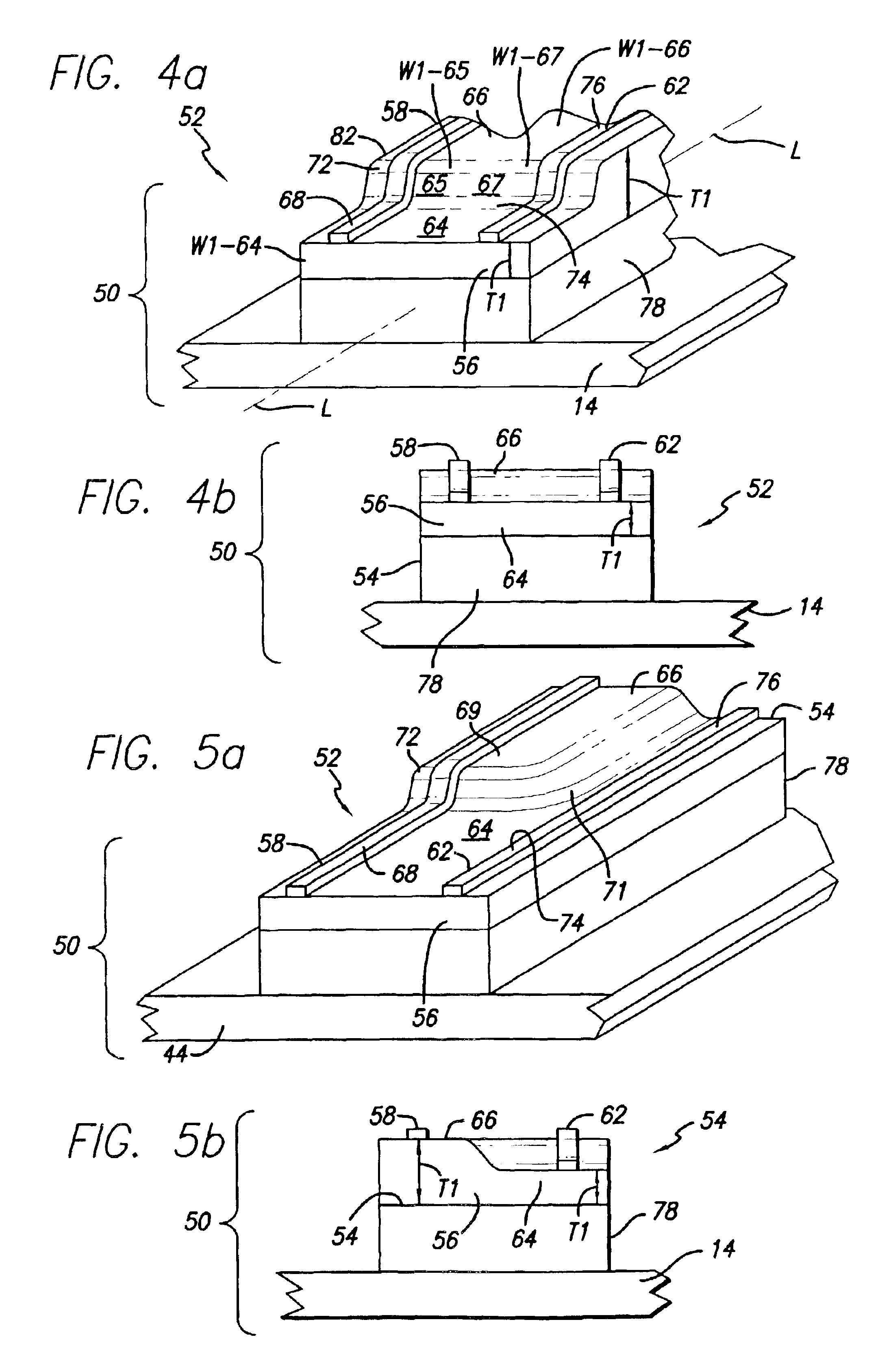
[0022]each trace conductor extends longitudinally and includes a series of longitudinally distributed local portions including a longitudinally extending first local trace conductor portion, the first local trace conductor portion being varied in thickness relative to local trace conductor portions distally, proximally or laterally adjacent thereto to increase or decrease the volume of the varied trace conductor spaced from the metal member selectively in the region of the variation in thickness in circuit impedance varying relation;
[0023]each trace conductor extends longitudinally and includes a series of longitudinally distributed local portions including a longitudinally extending first local trace conductor portion, the first local trace conductor portion being varied in width relative to local trace conductor portions distally, proximally or laterally adjacent thereto to increase or decrease the volume of the varied trace conductor spaced from the metal member selectively in the region of the variation in width in circuit impedance varying relation; and

Problems solved by technology

As set forth hereinafter there are disadvantages to the same thickness of insulative layer at the read circuit conductors as at the write circuit conductors, especially in blocking achievement of a different impedance for these circuits.
A further problem of impedance control exists, however, occasioned by the irregular nature of the suspension structures, design requirements related to geometry of the traces, and other causes that effect an unintended and undesired variation in impedance and a consequent unwanted degradation in signal integrity.

Method used


Image

  • Trace flexure suspension with differential insulator and trace structures for locally tailoring impedance
  • Trace flexure suspension with differential insulator and trace structures for locally tailoring impedance
  • Trace flexure suspension with differential insulator and trace structures for locally tailoring impedance

Examples


Embodiment Construction

[0066]As noted briefly above, trace flexures or wireless flexures have been built with either a subtractive process or an additive process that provides a planar device in which the stainless steel layer or load beam (if used), the insulative layer, usually a dielectric polyimide film layer, and the trace conductors, usually conductive copper layers are all essentially uniform thickness throughout their extents. The polyimide layer is the same thickness everywhere on a single part within manufacturing tolerances, and there has been no profiling in the insulative layer thickness by design. This is also true of the other, e.g. the conductor layers.

[0067]The electrical properties of the wireless flexure are a function of the thickness of the layers, the dielectric and physical material properties of each material, and the geometry, or mechanical layout, of each layer.

[0068]In calculating the capacitance C of a wireless flexure, one takes into consideration the spacing between the condu...


PUM


Abstract

A novel flexure or interconnect for a disk drive suspension having a locally different thickness and / or width of insulative layer and a locally different thickness, width and / or relative spacing in its trace conductors to vary capacitance and circuit impedance values accordingly to locally desirable different and optimum values for the type of circuit and the suspension features.

Description

CROSS-REFERENCE TO RELATED APPLICATIONS[0001]This application is a continuation-in-part of application Ser. No. 09 / 896,500, filed Jun. 28, 2001, now U.S. Pat. No. 6,424,500, issued Jul. 23, 2002, which application is continuation of application Ser. No. 09 / 592,140, filed Jun. 12, 2000, now U.S. Pat. No. 6,414,820, issued Jul. 2, 2002, which application claims the benefit of U.S. Provisional Application Ser. No. 60 / 184,684, filed Feb. 24, 2000. The disclosures of each and all of these applications are incorporated herein by this reference. This application further claims the benefit of U.S. Provisional Application Ser. No. 60 / 377,000, filed Apr. 30, 2002.STATEMENT REGARDING FEDERALLY SPONSORED RESEARCH OR DEVELOPMENT[0002]Not ApplicableREFERENCE TO A MICROFICHE APPENDIX[0003]Not ApplicableBACKGROUND OF THE INVENTION[0004]1. Field of the Invention[0005]This invention relates to disk drive suspensions, and more particularly, to a disk drive suspension and wireless electrical interconne...

Claims


Application Information

Patent Timeline
IPC IPC(8): G11B5/48G11B5/02G11B5/00
CPCG11B5/486G11B5/02G11B2005/001G11B5/012G11B5/484
Inventor COON, WARRENCUEVAS, RAFAEL
Owner MAGNECOMP
Learn More