Stable solid state raman laser and a method of operating same

a solid-state raman laser and stable technology, applied in the direction of laser details, optical resonator shape and construction, instruments, etc., can solve the problems of power drift, difficult to design solid-state raman lasers, complex design and operation, etc., to avoid optical damage to resonator components, maintain cavity stability, and maintain cavity stability

Inactive Publication Date: 2005-05-31
MACQUARIE UNIV
View PDF17 Cites 33 Cited by
  • Summary
  • Abstract
  • Description
  • Claims
  • Application Information

AI Technical Summary

Benefits of technology

[0013]wherein at least one parameter selected from the group consisting of (i) the position of the laser material relative to the position of the Raman medium in the cavity, (ii) the length of the cavity and (iii) the curvature of at least one of the reflectors, is selected such that changes in the focal lengths of both the laser material and the Raman medium as a result of thermal effects in the laser material and the Raman medium during operation of the laser do not substantially cause instability in the power of the output Raman laser beam.
[0059]the method including operating the laser such that a beam waist and resonator mode sizes of the laser material and the Raman medium are such that the Raman laser operates in a desired output power range whilst maintaining cavity stability and avoiding optical damage of the resonator components.

Problems solved by technology

Solid-state Raman laser systems suffer from the problem however that they are complex in design and operation and it is generally difficult to design a solid-state Raman laser which is capable of being operated with stability from initial current input to the optical power pump source up to maximum current and over a long period of time.
If the laser system is not effectively stable, alignment and power drifts result.

Method used


Image

  • Stable solid state raman laser and a method of operating same
  • Stable solid state raman laser and a method of operating same
  • Stable solid state raman laser and a method of operating same

Examples


example 1

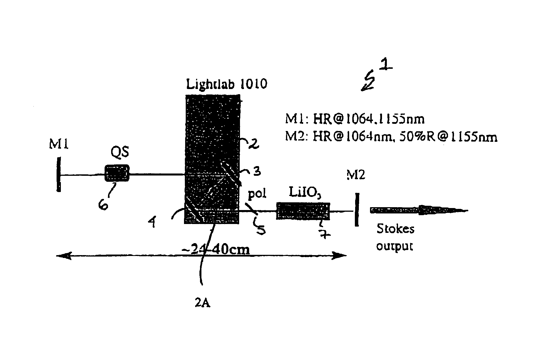
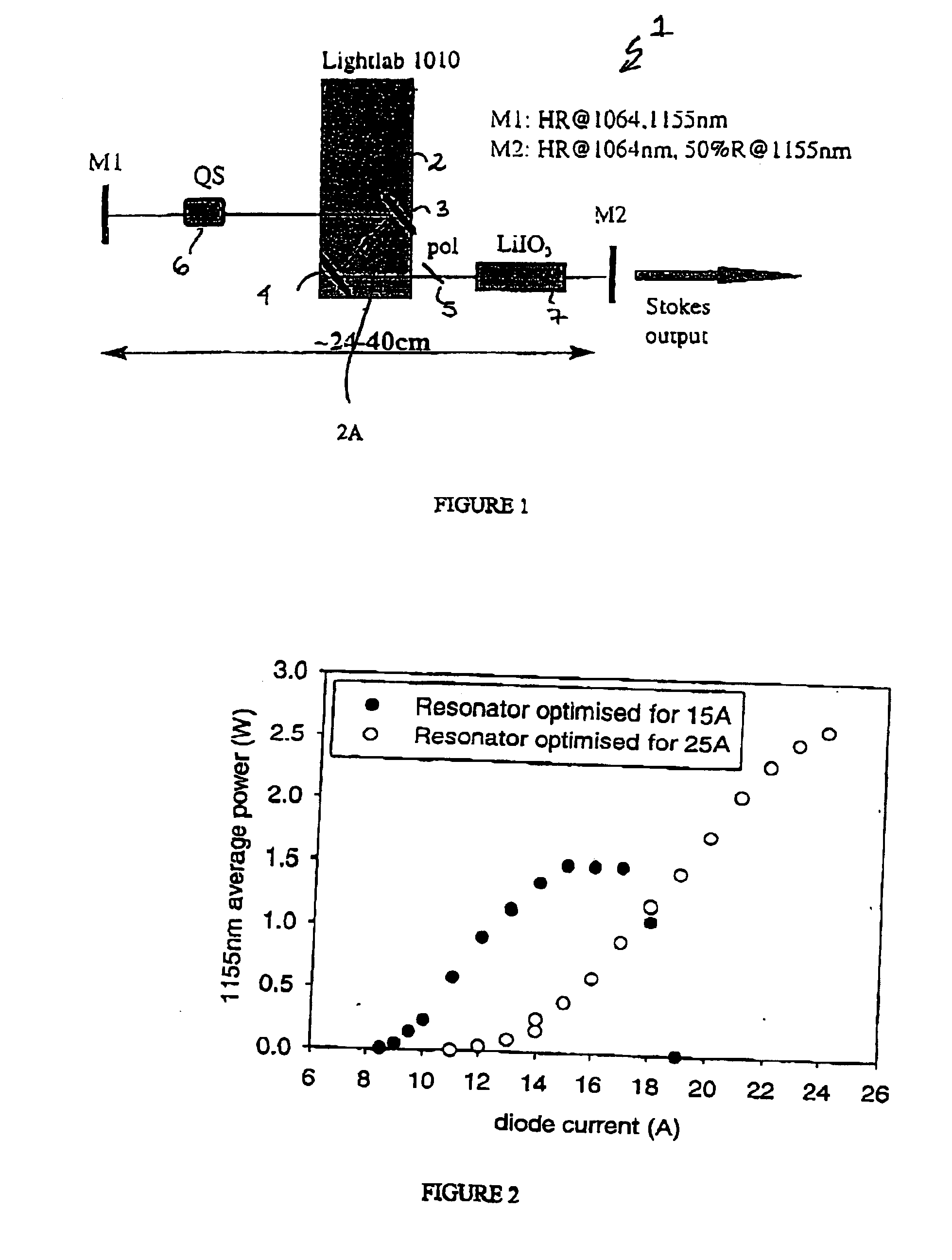
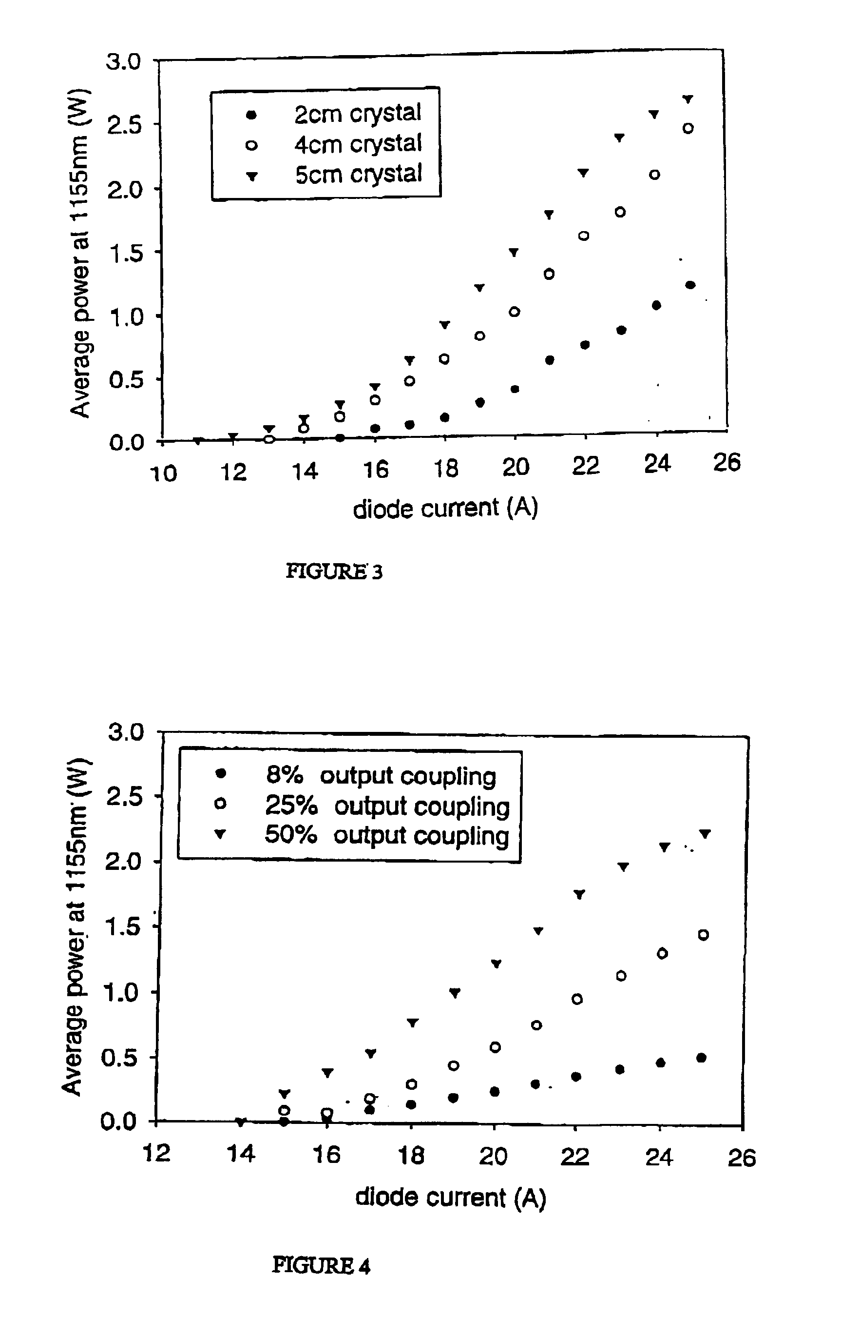
[0108]Experiments were conducted using a Raman Laser configuration as shown in FIG. 1. The Raman Laser 1 included a diode-pumped Nd:YAG laser employing a commercial pump module (Light Solutions LightLab 1010) 2. The module contained a Nd:YAG rod which was double-end pumped through dichroic turning mirrors 3 and 4. The mirror coatings for M1, M2, 3 and 4 were chosen to provide a high-Q resonator for the fundamental and a lower Q for the first Stokes. Mirror M1 had high reflectivity (>99.9%) at 1064-1160 nm and various output coupling mirrors M2 were used with high reflectivity at 1064 nm and transmissions from 8 to 50% at approximately 1155 nm. The laser was polarised using a one or two Brewster plates 5 and acousto-optically Q-switched 6 at 5-25 KHz to produce pulses at 1064 nm typically of duration of 20-50 ns depending on cavity configuration. A LiIO3 Raman crystal 7 was also located within the cavity to provide a Stokes wavelengths of approximately 1155 nm (1155.2-1155.5 nm as me...

example 2

[0123]With reference to FIG. 11, the output of the pump laser diode 1 which is a 25 W fibre-coupled diode laser is launched via fibre end receptacle 2 for 600 μm diameter, 0.22NA fibre, two lenses 3 and 4 into the laser crystal 5 which is a Nd:YAG (5 mm×5 mm diameter laser crystal with mirror coatings on end 1 (5A):HR at 1064-1160 nm, HT at 805 nm and end 25B: AR@1064-1160 nm). The pump spot size (beam radius) in the laser crystal is approximately 300 microns. The laser resonator is defined by the first coated plane face of the Nd:YAG laser crystal 5, the plane dichroic mirror 9 at 45 degrees (HR at 1064-1160 nm, HT@578 nm and the end mirror 11 (HR at 578, 1064 and approx 1155 nm) which has a radius of curvature of 300 nm. An LBO 4×4×15 mm crystal is used as the frequency doubling crystal and a LiO3 crystal is used as the Raman-active crystal. The optimum lengths of the two arms of the resonator are 150 mm (YAG crystal to 45 degree mirror) and 90 mm (45 degree mirror to end mirror)....

example 3

[0127]A small-scale Raman laser operating at 1197 nm was used. In the system used, the pump laser diode had relatively low output power. 1.6 W of 808 nm diode pump light was focused into a 2×2×1 mm Nd:YVO4 crystal. An acousto-optic Q-switch was used to produce the necessary high peak powers for the SRS process. The Raman-active crystal was Ba(NO3)2 which provided one of the highest Raman gains, having a Raman shift of 1047 cm−1. The optimum arrangement for the intra-cavity SRS conversion included using a 10 cm long cavity, with 10% output coupling at 1197 nm and a pulse repetition frequency of 32 kHz. The First Stokes output occurred at 1197 nm and up to 120 mW of output power was obtained.

[0128]A frequency-doubled small-scale Raman laser operating at 1197 nm was used. Preliminary measurements were made of intracavity-doubled First Stokes output using a 10 mm long piece of LBO cut for type one phase making. Up to 6 mW at 598 nm was achieved under non-optimised conditions. The cavity...


PUM

PropertyMeasurementUnit
wavelengthaaaaaaaaaa
diameteraaaaaaaaaa

Abstract

The present invention relates to a stable solid-state Raman laser, the solid-state Raman laser including a resonator cavity defined by at least two reflectors, a laser material located in the resonator cavity and capable of generating a cavity laser beam which propagates within the resonator cavity, a solid Raman medium located in the resonator cavity for shifting the frequency of the cavity laser beam to produce a Raman laser beam which propagates within the resonator cavity; and an output coupler for coupling and outputting the Raman laser beam from the resonator cavity, wherein at least one parameter selected from the group consisting of the position of the laser material relative to the position of the Raman medium in the cavity, the length of the cavity and the curvature of at least one of the reflectors, is selected such that changes in the focal lengths of both the laser material and the Raman medium as a result of thermal effects in the laser material and the Raman medium during operation of the laser do not substantially cause instability in the power of the output Raman laser beam. A method of maintaining stable operation of a solid state Raman laser is also described.

Description

[0001]This is the U.S. national phase of International Application No. PCT / AU01 / 00906 filed Jul. 26, 2001, the entire disclosure of which is incorporated herein by reference.TECHNICAL FIELD[0002]The present invention relates to a stable solid-state Raman laser and a method of maintaining stable operation of a solid-state Raman laser.BACKGROUND OF THE INVENTION[0003]Solid-state Raman lasers are a practical and efficient approach to optical frequency down conversion offering high (up to 70-80%) conversion efficiencies with respect to the pump laser power, excellent beam quality and ease of alignment In recent years use of crystals for stimulated Raman scattering (SRS) has been gaining interest because, in comparison with high-pressure gaseous and dye (liquid) Raman lasers, crystalline Raman lasers offer better gain, better thermal and mechanical properties, better reliability and the ability to operate at high pulse-repetition frequency. Further they are compatible with compact all-so...

Claims


Application Information

Patent Timeline
Patent Type & Authority Patents(United States)
IPC IPC(8): H01S3/30H01S3/13H01S3/11H01S3/113H01S3/108H01S3/136H01S3/08H01S3/139G02F1/37G02F1/35H01S3/109
CPCH01S3/30H01S3/08072H01S3/108H01S3/136H01S3/139H01S3/117
Inventor PASK, HELEN M.PIPER, JAMES A.
Owner MACQUARIE UNIV
Why Eureka
Try Eureka