
Electrical control system configuration method and apparatus

a technology of electrical control system and configuration method, applied in the direction of programme control, total factory control, instruments, etc., can solve the problems of inability to program control and monitor equipment in such a way, inability to identify and correct input process errors, and inability to achieve the effect of reducing the cost of programming procedur

Inactive Publication Date: 2005-05-31
ROCKWELL TECH
View PDF26 Cites 88 Cited by
  • Summary
  • Abstract
  • Description
  • Claims
  • Application Information

AI Technical Summary

Benefits of technology

[0006]The present invention provides a novel approach to configuring network programmable electrical components designed to respond to these needs. The technique may be applied in a wide range of systems, but is well-suited to industrial automation, and particularly well-suited to power control components, such as motor starters, motor drives, programmable relays, and so forth. The components may be included in limited systems or in expansive systems comprising may components at a variety of node addresses and physical locations within an installation.

Problems solved by technology

However, no technique is available at present for programming control and monitoring equipment in such a way as to provide enhanced monitoring, reporting, and distributed control functions.
Where limited programmability is provided in conventional industrial automation systems, these devices must generally be manually programmed individually.
This programming procedure is not only costly in terms of time and manpower, but can lead to errors in the input process which must be identified and corrected.
Following initial programming, such systems are not particularly well-suited to reprogramming or reconfiguration, but require similar manual and individual data input.

Method used


Image

  • Electrical control system configuration method and apparatus
  • Electrical control system configuration method and apparatus
  • Electrical control system configuration method and apparatus

Examples


Embodiment Construction

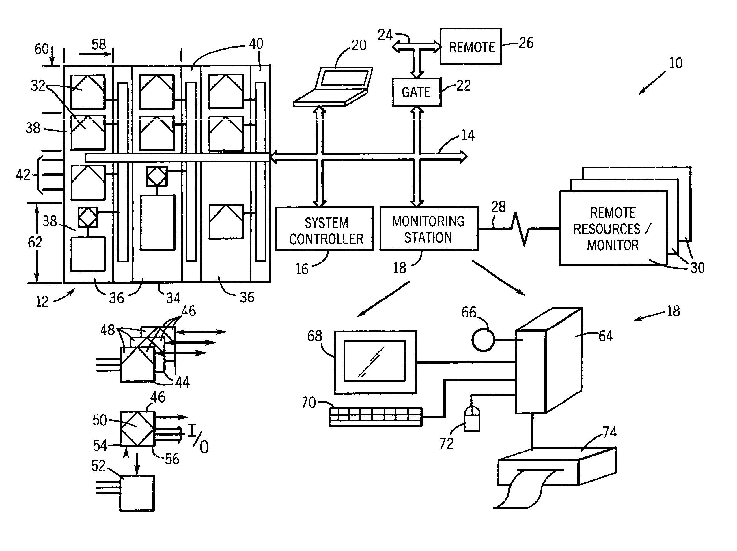
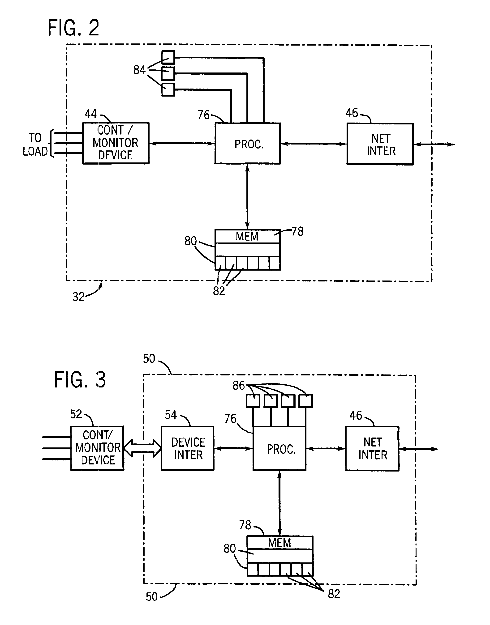
[0023]Turning now to the drawings, and referring first to FIG. 1, a control and monitoring system 10 is illustrated as including a component assembly 12, and a network 14 for transmitting data to and from components of the assembly. While the component assembly 12 may take many forms, and include devices for accomplishing many different and varied purposes, in a preferred implementation, the component assembly includes electrical control and monitoring equipment for regulating application of electrical power to loads. In particular, the components may include motor starters, motor controllers, variable frequency drives, relays, protective devices such as circuit breakers, programmable logic controllers, and so forth. In the industrial automation field, such component assemblies are commonly referred to as motor control centers (MCC's).

[0024]In addition to the component assembly and network, system 10 includes a system controller 16 and a monitoring station 18. System controller 16 m...


PUM


Abstract

A technique for configuring programmable, networked electrical components of a system includes downloading data into each component from a configurator, based upon a database for the system. The components include memory objects which are designed to store data descriptive of the system, the component, the component location in the system, and the component configuration. The configurator may load the information prior to, during or following assembly of the components in the system. The configurator may also modify system and component configurations following installation of the system by modifying the data downloaded into the individual components.

Description

BACKGROUND OF THE INVENTION[0001]The present invention relates generally to the field of electrical control and monitoring systems, such as systems used in industry for controlling application of electrical power to loads. More particularly, the invention relates to a technique for configuring programmable devices coupled to a network in a control and monitoring system.[0002]In the field of industrial automation, many types of components, switch gear, protective devices, and so forth are known for regulating application of power to electrical loads. Such loads typically include electric motors, valves, and actuators. Inputs to the control systems may include sensors, and operator-generated signals which may work in conjunction with a pre-established program for carrying out either with or without operator intervention, automated processes. By way of example, motor control centers are employed in many factories for protecting motors and similar devices, and for regulating speeds, ene...

Claims


Application Information

Patent Timeline
Patent Type & Authority Patents(United States)
IPC IPC(8): G06F19/00G05B19/042
CPCG05B19/0426Y10S388/909Y02P90/02
Inventor JENSEN, DAVERETLICH, KEVINKLEIN, LOU
Owner ROCKWELL TECH
Learn More