Al technical title is built by PatSnap Al team. It summarizes the technical point description of the patent document.
a hydrodynamic surface and low-drag technology, applied in the field of hydrodynamics, to achieve the effect of reducing the drag of high-speed hydrofoil cra
Inactive Publication Date: 2005-06-07
LANG THOMAS G +1
View PDF43 Cites 29 Cited by
Summary
Abstract
Description
Claims
Application Information
AI Technical Summary
This helps you quickly interpret patents by identifying the three key elements:
Problems solved by technology
Method used
Benefits of technology
[0006]A primary objective of this invention is to reduce the drag of high-speed hydrofoil craft by forming a closed gas cavity on each side of each lifting hydrofoil, forming an open cavity on each side of each support strut, and by covering at least one side of each propulsor blade with a cavity.
[0007]A preferred design is a hydrofoil craft that has one highly-swept-back v-hydrofoil in planform, supported by three swept struts, powered by two superventilating propellers wherein each drive shaft is located within a strut, and wherein the hydrofoil sweep back eliminates cavitation and reduces craft motion in waves.
[0008]Another objective is to efficiently control the lift of hydrofoil cross sections having closed cavities by using trailing edge flaps, optional leading edge flaps, and optional means for controlling gas flow rates.
[0009]Other objectives are to efficiently initiate cavities by introducing discontinuities to separate the water boundary layer in various ways, efficiently distribute the gas to each cavity, control the cavities, and separate adjacent cavities with different kinds of fences.
[0010]Still another objective is to minimize cavity drag on underwater surfaces by closing the cavities as smoothly as possible by minimizing the contact angle between the cavity and the surface. Another objective is to further minimize cavity drag by adding parallel ridges in the vicinity of cavity closure to reduce forward splash and thereby minimize gas entrainment out of the cavity.
Problems solved by technology
The problem is how to design underwater surfaces to make full use of cavities to reduce drag.
Method used
Image
Click on the blue label to locate the original text in one second.
Reading with bidirectional positioning of images and text.
Examples
Embodiment Construction
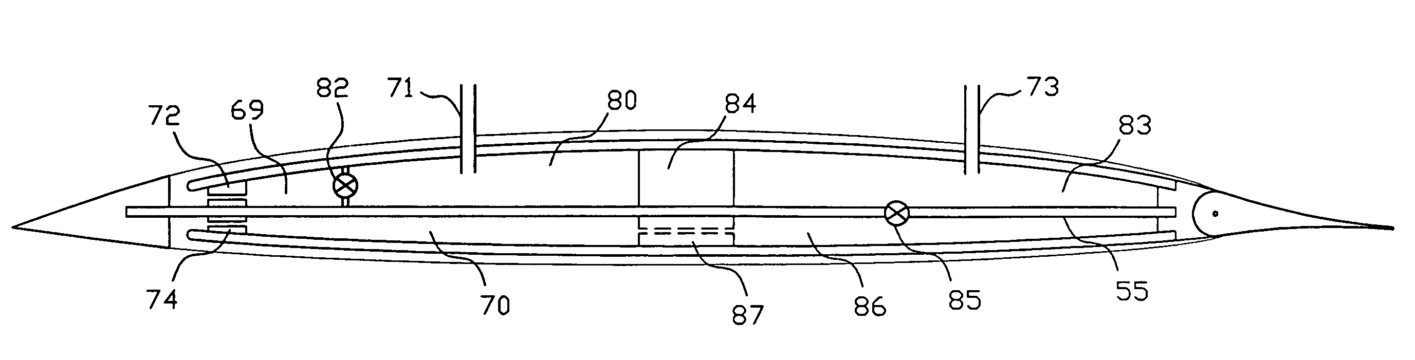
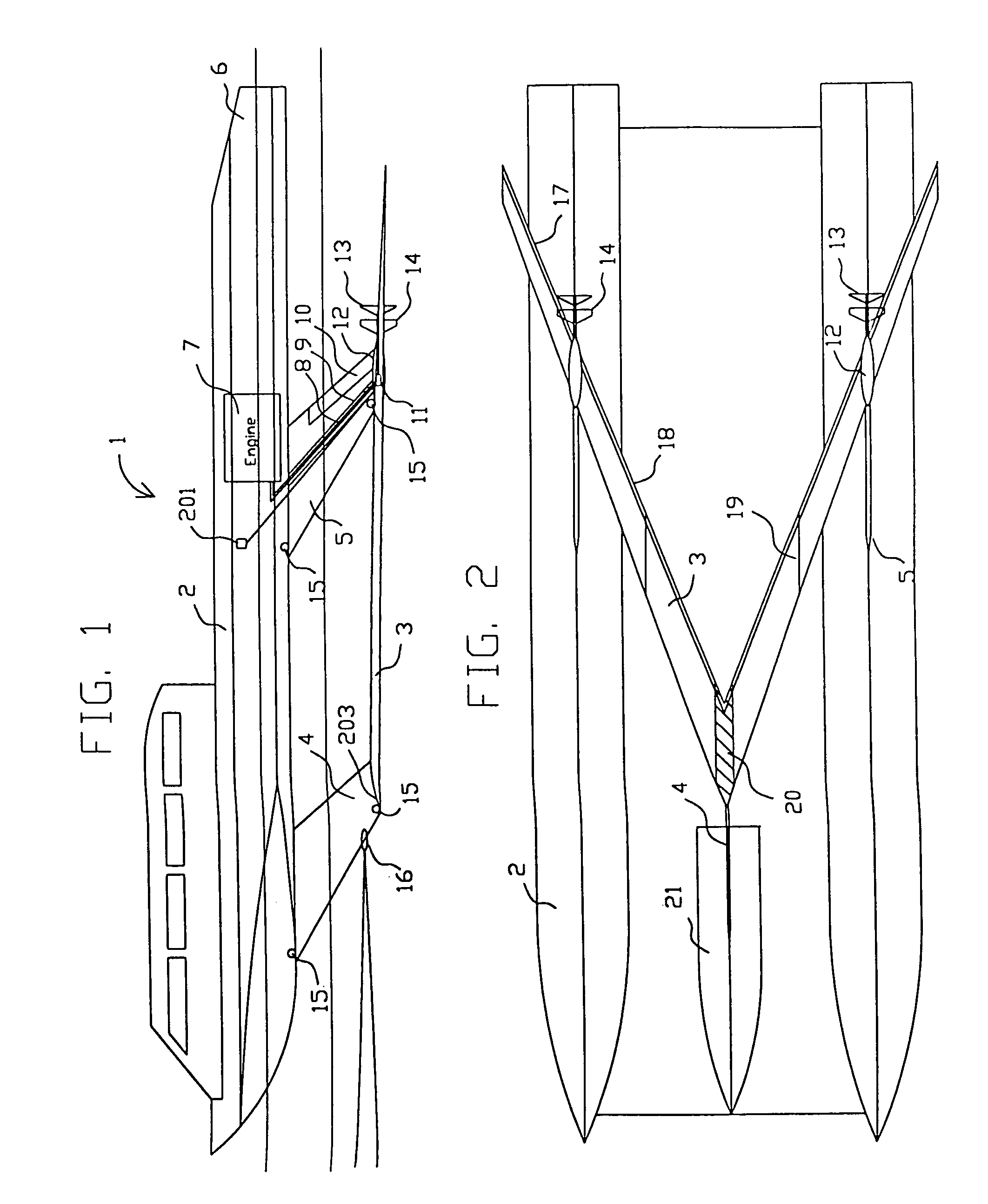
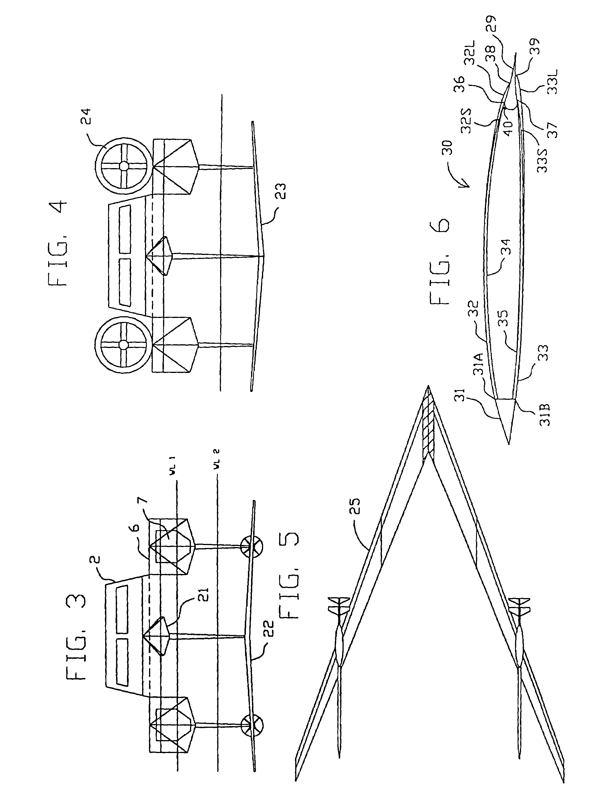
[0056]In FIGS. 1 and 2, the hull 2 of hydrofoil craft 1 is supported above water by forward strut 4 and two aft struts 5 which are attached to lifting v-hydrofoil 3. The propulsion system consists of engine 7 in each catamaran hull 6 that drives shaft 8 located in duct 9 of strut 5, thereby eliminating drag on the drive shaft. Shaft 8 enters gearbox 11 located inside pod 12 to drive propeller 13. Pre-spin vanes 14 rotate the water flow entering the propeller so that the water flow leaves the propeller without significant rotation, thereby increasing propeller efficiency. This hydrofoil and propulsion arrangement is equally applicable to monohulls, trimarans or other hull shapes, and applies to one or more support struts, engines and propulsors. Each strut can either be swept back, as shown, or unswept, or swept forward. Strut sweep reduces strut spray drag, and reduces strut side force in beam waves. Hydrofoil sweep reduces susceptibility to cavitation, and reduces craft vertical mo...
PUM
Abstract
The invention relates to the use of gas cavities to reduce frictional drag on underwater surfaces such as hydrofoils, struts, fins, rudders, keels, propeller blades, ship hulls, underwater bodies, and wetted surfaces in general. Each gas-filled cavity is formed behind a discontinuity in the surface that causes the water boundary layer to separate from the surface. Gas is ejected into a region behind the discontinuity to fill the cavity; the gas can be air. If a cavity is open to the atmosphere, then air can typically fill the cavity naturally without air ejection. Cavities can either be closed or open. A low drag hydrofoil may have a closed cavity on one side, and an open cavity on the other side. For closed cavities, the underlying surface can be shaped to minimize cavity closure drag. Various ways to generate cavities, change hydrodynamic forces, and duct gas internally on hydrofoils and struts with cavities are covered. Different designs of hydrofoil boats, hydrofoil ships and ship hulls that are amenable to drag reduction are presented.
Description
[0001]This is a continuation-in-part of U.S. application Ser. No. 09 / 689,698, filed Oct. 13, 2000, now U.S. Pat. No. 6,439,148 which is a division of U.S. application Ser. No. 08 / 948,242, filed Oct. 9, 1997, now U.S. Pat No. 6,167,829.[0002]This invention was made with Government support under DAAH01-96-C-R228, and DAAH01-98-C-R115 awarded by the Defense Advanced Research Projects Agency. The Government has certain rights in certain claims of this invention.BACKGROUND OF THE INVENTION[0003]This invention applies to the field of hydrodynamics, and relates to the use of gas cavities to reduce the frictional drag of hydrofoil craft, ship hulls and underwater surfaces in general. Using cavities to reduce frictional drag is covered in U.S. Pats. No. 3,077,173 (1963) and No. 3,109,495 (1963) for base-vented and side-vented hydrofoils, U.S. Pat. No. 3,205,846 (1965) for torpedoes, and U.S. Pat. No. 6,167,829 (2001), together with a pending continuation of that patent, for submerged surface...
Claims
Application Information
Patent Timeline
Application Date:The date an application was filed.
Publication Date:The date a patent or application was officially published.
First Publication Date:The earliest publication date of a patent with the same application number.
Issue Date:Publication date of the patent grant document.
PCT Entry Date:The Entry date of PCT National Phase.
Estimated Expiry Date:The statutory expiry date of a patent right according to the Patent Law, and it is the longest term of protection that the patent right can achieve without the termination of the patent right due to other reasons(Term extension factor has been taken into account ).
Invalid Date:Actual expiry date is based on effective date or publication date of legal transaction data of invalid patent.