Method of designing ophthalmic lens and ophthalmic lens produced by the method
a technology of which is applied in the field of designing ophthalmic lenses and ophthalmic lenses produced by the method, can solve the problems of eye deterioration and optical characteristic of the optical system consisting of lenses, and achieve the effect of improving visual acuity and stability
- Summary
- Abstract
- Description
- Claims
- Application Information
AI Technical Summary
Benefits of technology
Problems solved by technology
Method used
Image
Examples
first embodiment
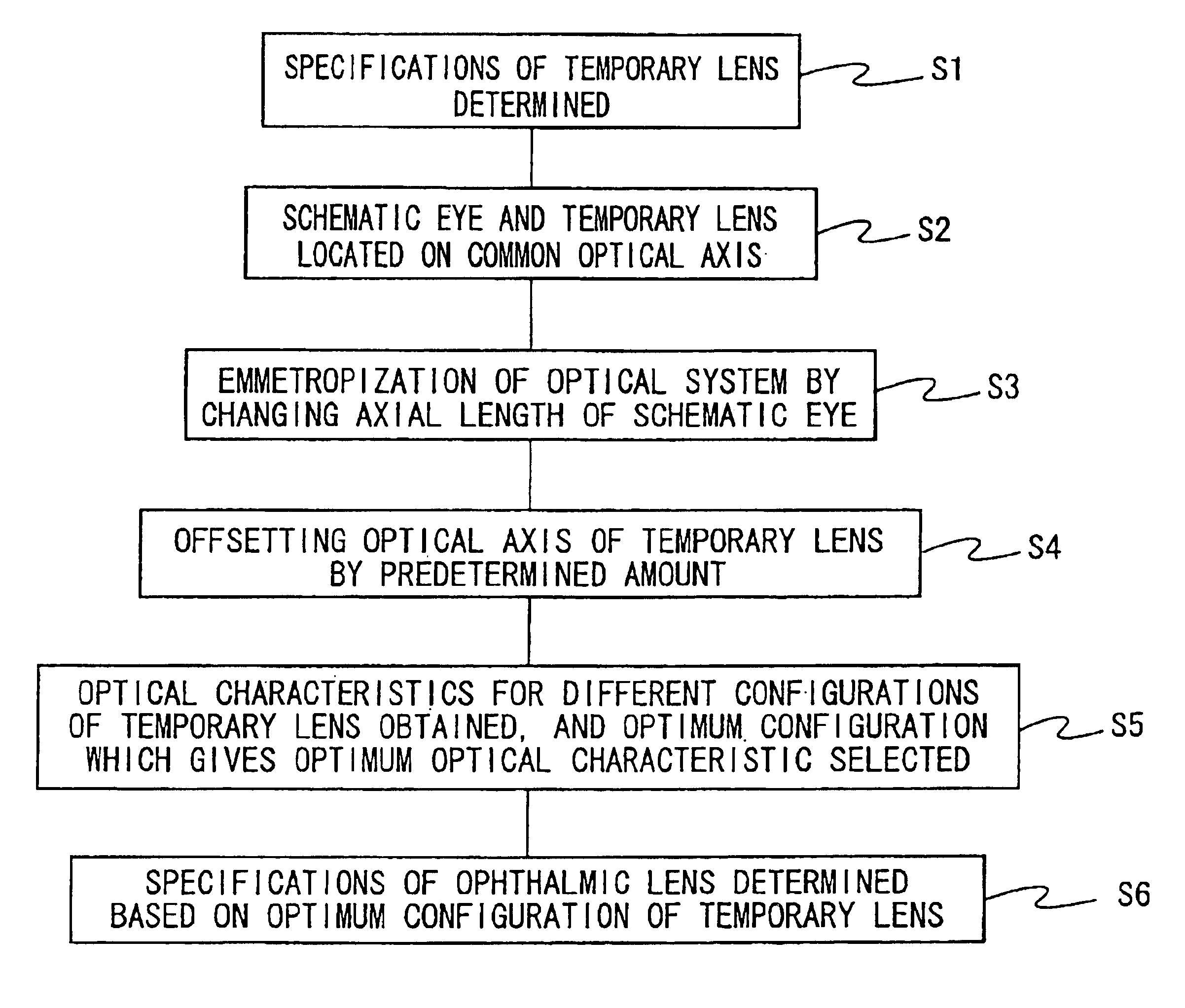
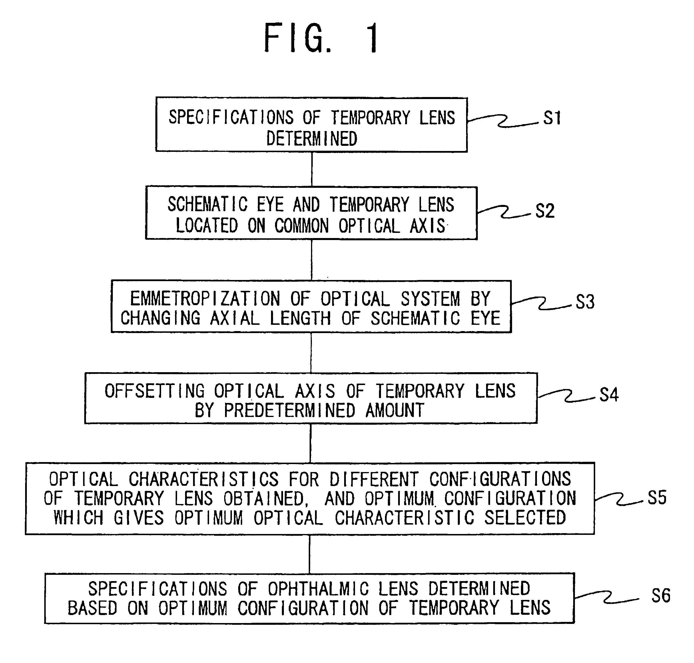
[0034]Referring first to a flow chart of FIG. 1, there are shown steps for designing an ophthalmic lens according to the present invention. The flow chart starts with step S1 in which the specifications of a temporary or trial lens which gives the intended ophthalmic lens are determined such that the temporary lens gives an optical power required by a wearer of the ophthalmic lens. The optical power required by the lens wearer is determined by various examinations of the eye to which the intended ophthalmic lens is applied, using various known devices. Based on the knowledge of those skilled in the art of the ophthalmic lens, the configuration of the temporary lens is temporarily determined, and the specifications of the temporary lens such as a base curve (BC) of a back surface, a front curve (FC) of a front surface, a diameter (DIA), a center thickness (CT), an aspheric coefficient, etc. are determined by taking into account a refractive index of a lens material.
[0035]Step S1 is f...
second embodiment
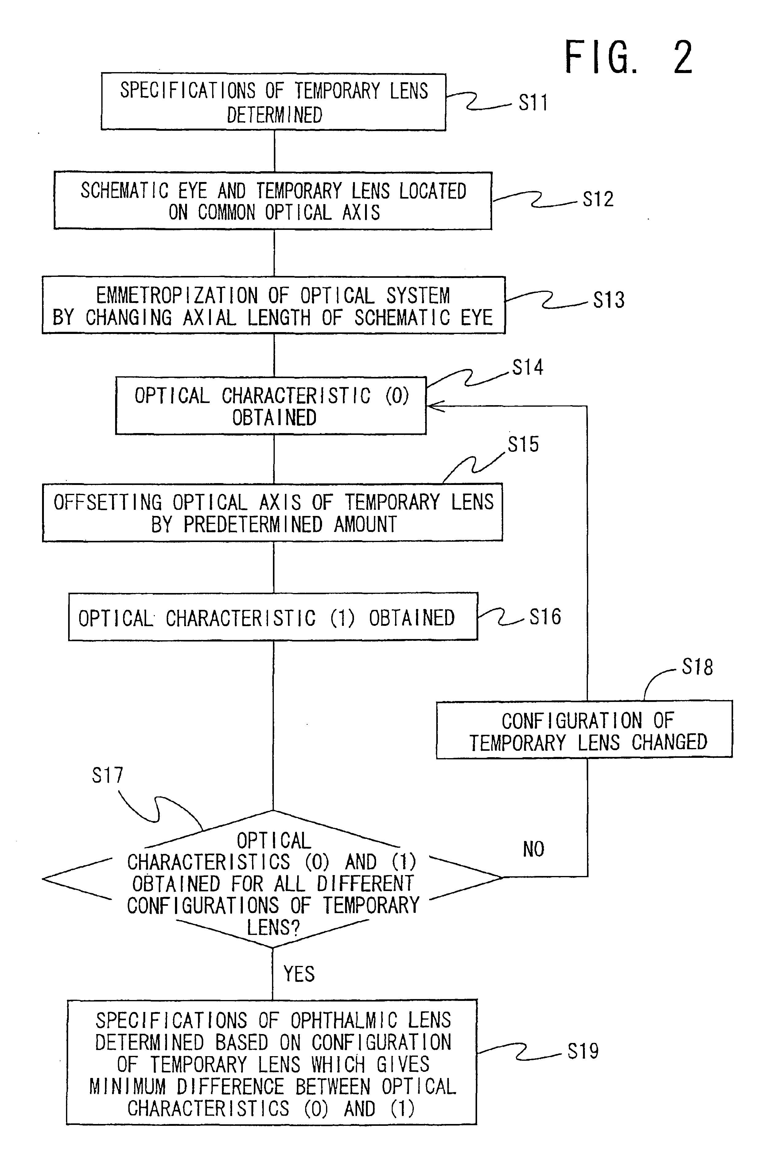
[0066]Referring next to the flow chart of FIG. 2, there is shown another method of designing an ophthalmic lens according to the invention.
[0067]The flow chart of FIG. 2 is identical with the flow chart of FIG. 1, except for steps S14 through S18. Steps S11 through S13 and step S19 in the flow chart of FIG. 2 correspond to Steps S1 through S3 and step S6 in the flow chart of FIG. 1, respectively.
[0068]In steps S11 through S13 in the flow chart of FIG. 2 corresponding to steps S1 through S3 in the flow chart of FIG. 1, the temporary lens is applied to the prescribed schematic eye such that the optical axis of the temporary lens is aligned with that of the schematic eye, and the optical system consisting of the temporary lens and the schematic eye is subjected to the emmetropization. In the following step S14, the optical characteristic (0) of the optical system is obtained as a reference characteristic.
[0069]Step S14 is followed by step S15 in which the position of the optical axis o...
third embodiment
[0072]If the offset amount of the optical axis of the temporary lens from the optical axis of the schematic eye is relatively large, the offset amount may be divided into a plurality of divisions, and the optical characteristic of the optical system consisting of the temporary lens and schematic eye is obtained at an end point of each of the plurality of divisions. In this case, an effective lens characteristic can be obtained by taking into account a plurality of optical characteristics obtained at the respective end points of the plurality of divisions of the offset amount. One example of this arrangement is shown in a flow chart of FIG. 3 according to the invention.
[0073]In steps S21 through S23 of the flow chart of FIG. 3 corresponding to steps S1 through S3 of the flow chart of FIG. 1, the emmetropization of the optical system consisting of the schematic eye and the temporary lens is effected with the optical axes of the schematic eye and the temporary lens being aligned with e...
PUM
 Abstract
Description
Claims
Application Information
 - R&D
- Intellectual Property
- Life Sciences
- Materials
- Tech Scout
- Unparalleled Data Quality
- Higher Quality Content
- 60% Fewer Hallucinations
Browse by: Latest US Patents, China's latest patents, Technical Efficacy Thesaurus, Application Domain, Technology Topic, Popular Technical Reports.
© 2025 PatSnap. All rights reserved.Legal|Privacy policy|Modern Slavery Act Transparency Statement|Sitemap|About US| Contact US: help@patsnap.com


