Reduced-noise plethysmograph

a plethysmograph and reduced noise technology, applied in the field of plethysmographs, can solve the problems of adversely affecting the accuracy of recorded data, still occurring noise level, adversely affecting test, etc., and achieve the effect of reducing the effect of changes in exterior air, minimizing the effect of pressure changes, and improving the accuracy of pressure readings by the transducer

Active Publication Date: 2005-06-07
DATA SCI INT
View PDF11 Cites 13 Cited by
  • Summary
  • Abstract
  • Description
  • Claims
  • Application Information

AI Technical Summary

Benefits of technology

[0015]In accordance with the present invention, noise affecting accurate readings of pressure changes within the test chamber is further reduced by the addition of a manifold to the plethysmograph. As used herein, the term “manifold” is used to define an air passageway or conduit adapted to communicate with the airflow openings into the test and reference chambers, and an exterior airflow opening from the exterior of the manifold into the passageway. The passageway can be in the form of a housing that encloses the inlets, tubes that separately connect to the chamber openings and to a common exterior opening, or conduits drilled within a solid block of material to connect the chamber airflow openings and the exterior airflow opening. Preferably, the distances from the exterior airflow opening to the test and reference chamber airflow openings are approximately the same distance, so that air entering the exterior airflow opening will have about the same distance to travel to reach the test and reference chamber airflow openings.
[0016]It has been found that addition of this manifold further minimizes the effect of changes in exterior air, since the air enters both chambers from a common opening

Problems solved by technology

This non-chamber originated air pressure variation, known as background noise or simply noise, can adversely affect the accuracy of the recorded data, since

Method used


Image

  • Reduced-noise plethysmograph
  • Reduced-noise plethysmograph
  • Reduced-noise plethysmograph

Examples


Embodiment Construction

[0026]In the following description, terms such as horizontal, upright, vertical, above, below, beneath, and the like, are used solely for the purpose of clarity in illustrating the invention, and should not be taken as words of limitation. The drawings are for the purpose of illustrating the invention and are not intended to be to scale.

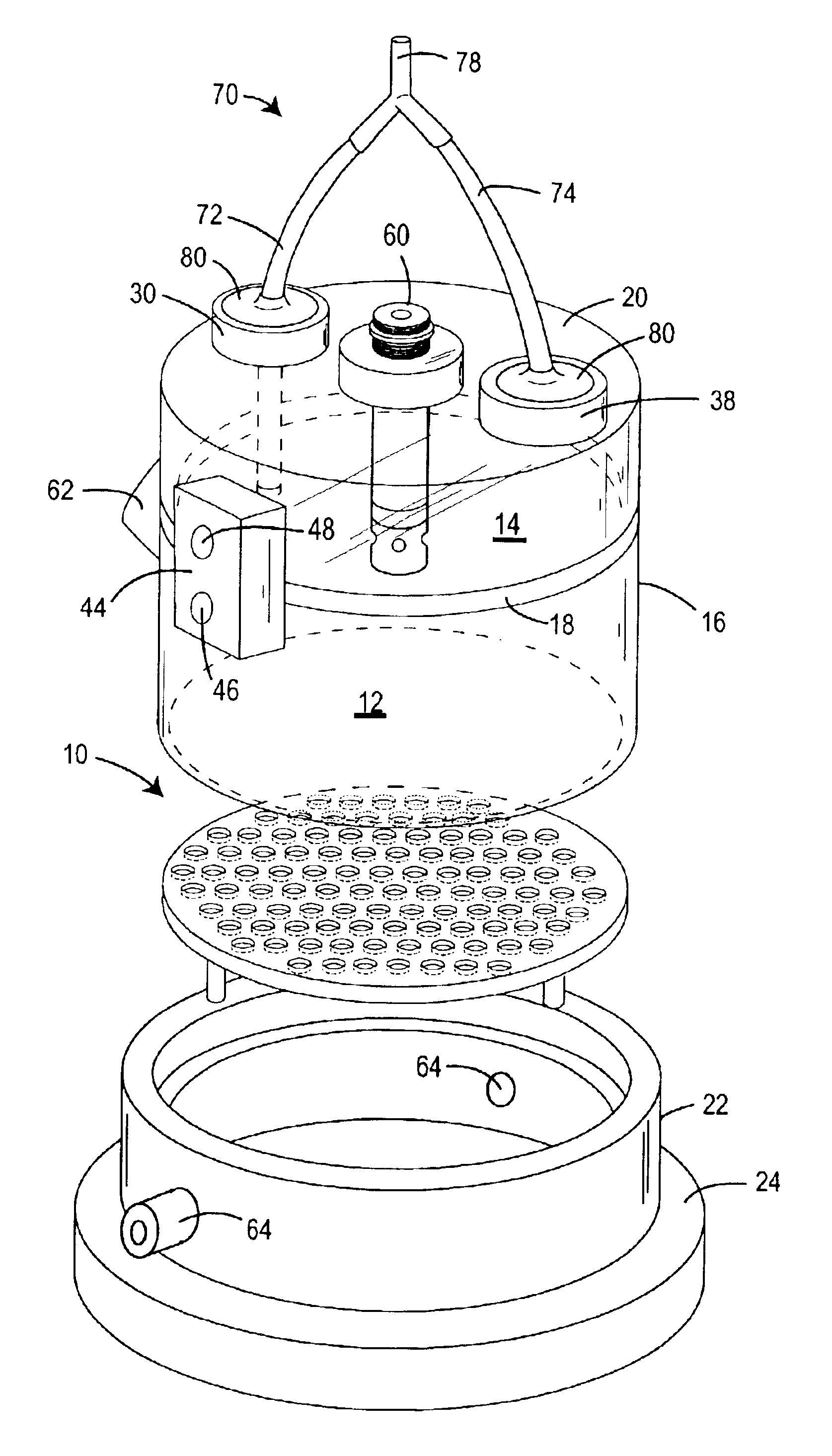
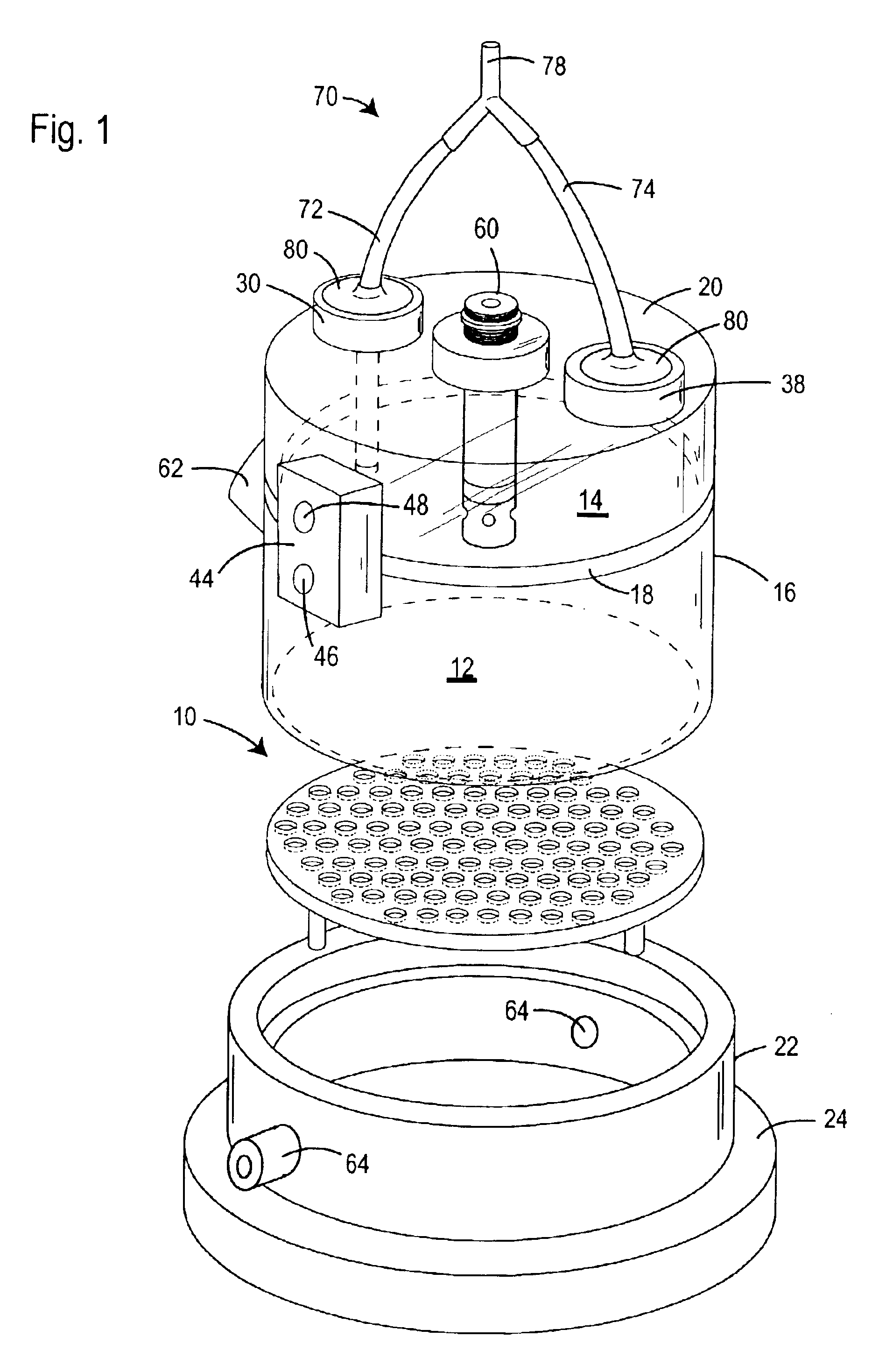
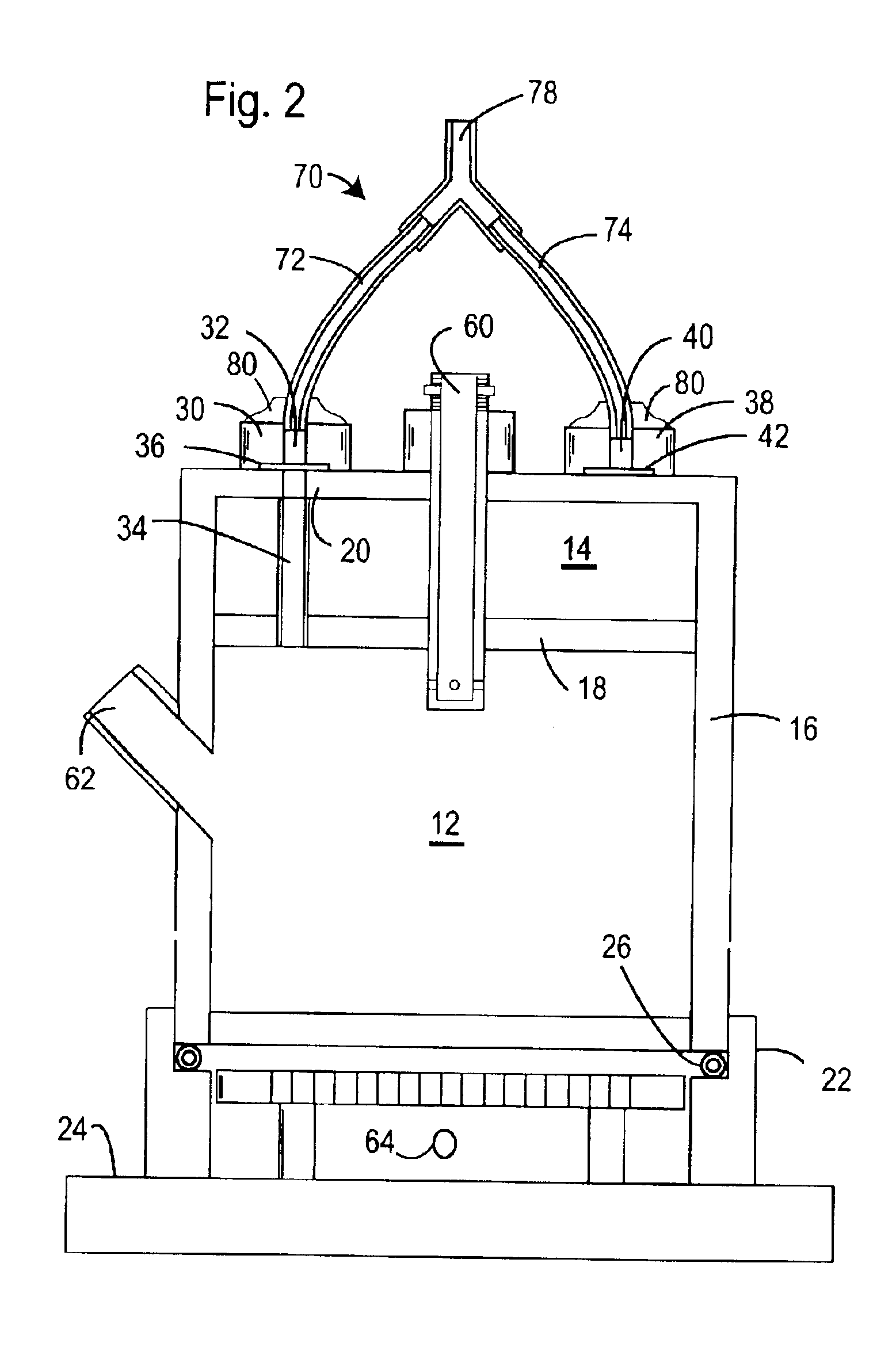
[0027]FIGS. 1 and 2 illustrate a preferred embodiment of the invention comprised of a plethysmograph, generally 10, that includes a test chamber 12 and a reference chamber 14. Chambers 12 and 14 share a common cylindrical wall 16 that is divided into the two chambers by a common separator wall 18. A top wall 20 covers reference chamber 14. The lower end of common wall 16 is fitted into a cylindrical base wall 22, which rests on a footed base 24. An O-ring 26 around the exterior of wall 16 provides a seal between the walls 16 and base wall 22.

[0028]Test chamber pneumotach 30 mounted on top wall 20 includes an airflow inlet 32 in communication with a t...


PUM


Abstract

The accuracy of measurements of changes in air volumes within a plethysmograph is improved by addition of a manifold to provide a common source of exterior air to the plethysmograph test and reference chamber. The preferred plethysmograph includes test and reference chambers divided by a common separator wall, pneumotachs in communication with the chambers, and a differential pressure transducer having a first inlet in communication with the test chamber and a second inlet in communication with the reference chamber. The manifold includes an exterior air inlet and a passageway extending between the two pneumotachs and the air inlet. The passageway may be in the form of separate tubes or conduits, or a common housing covering the pneumotachs. Preferably, the distances from the exterior air inlets to the two pneumotachs are approximately the same.

Description

BACKGROUND OF THE INVENTION[0001](1) Field of the Invention[0002]The present invention relates to plethysmographs used for measuring changes in air volume, such as in non-invasive pulmonary testing of small animals, and in particular to plethysmographs in which transducer noise is substantially reduced, improving the accuracy of test data.[0003](2) Description of the Prior Art[0004]Plethysmographs are used in research to collect data relating to changes in air pressure within a test chamber. An example of such data is pulmonary data from small animals, such as mice. Most plethysmographs are comprised of a test chamber to enclose the test subject, a reference chamber, and a differential pressure transducer connected to the two chambers, e.g., via tubing extending from a port in each chamber to the transducer. Both chambers are in communication with the ambient air, i.e., the air within the room where the tests are being conducted, through restricted airflow openings, or pneumotachs.[...

Claims


Application Information

Patent Timeline
IPC IPC(8): A61B5/08
CPCA61B5/0806
Inventor LOMASK, JOSEPH
Owner DATA SCI INT
Why Eureka
Try Eureka