
Electrostatic precipitator with internal power supply

a technology of electrostatic precipitators and power supplies, applied in the direction of electric supply techniques, machines/engines, separation processes, etc., can solve the problems and achieve the effect of reducing the insulating properties of such sections and preventing moisture and contaminant accumulation

Inactive Publication Date: 2005-06-07
CUMMINS FILTRATION INC +1
View PDF29 Cites 27 Cited by
  • Summary
  • Abstract
  • Description
  • Claims
  • Application Information

AI Technical Summary

Benefits of technology

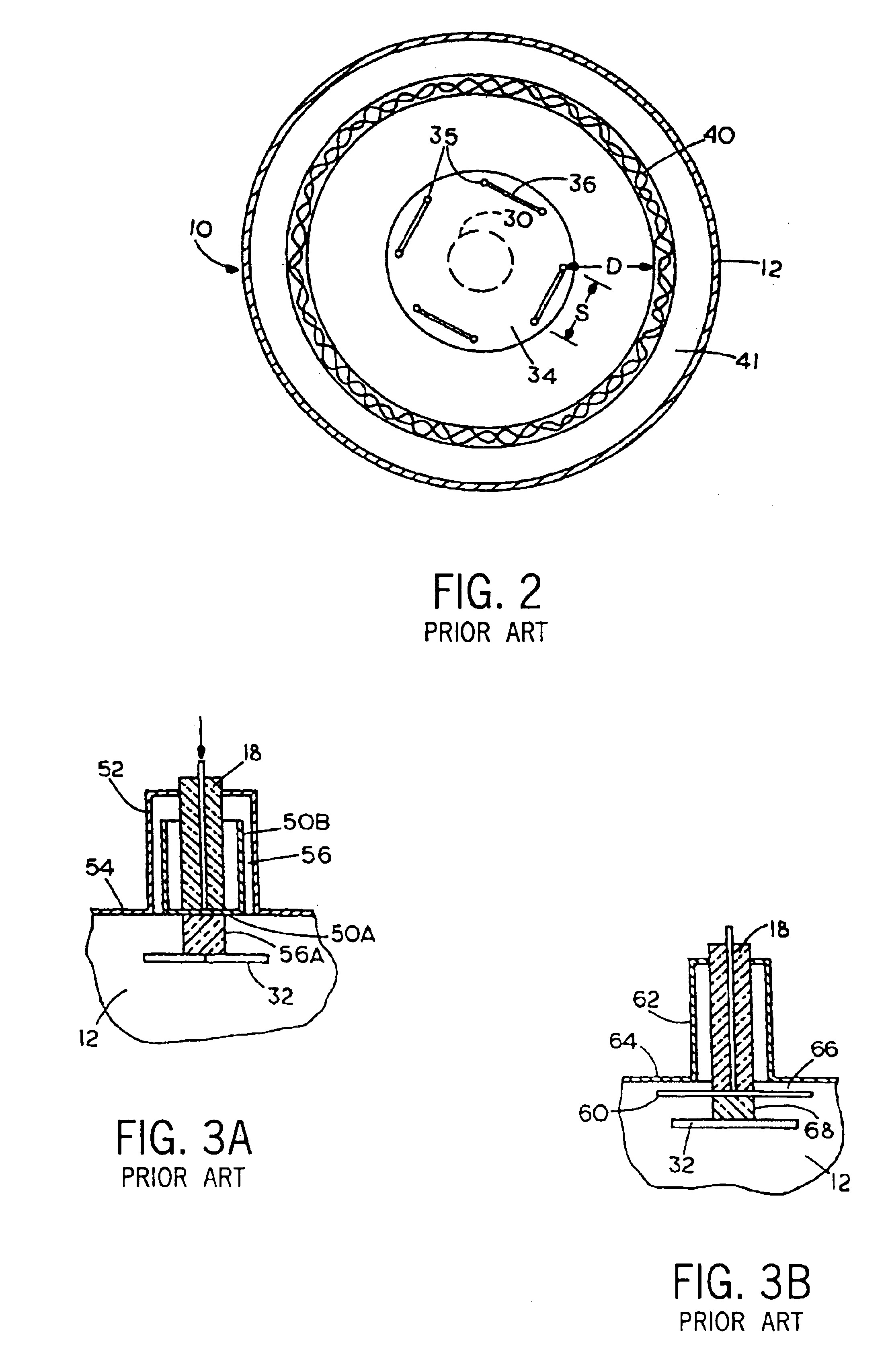
[0004]In known electrostatic precipitators, the high voltage power supply is placed outside the collector section, either remotely mounted or mounted directly to the collector in some manner. In either of these configurations, a high voltage electrode rod or lead must pass-through an insulator section to deliver the high voltage to the corona producing discharge electrode assembly. The insulator may also be heated to prevent moisture and contaminant accumulation on the insulating surface, thereby reducing the insulating properties of such section.
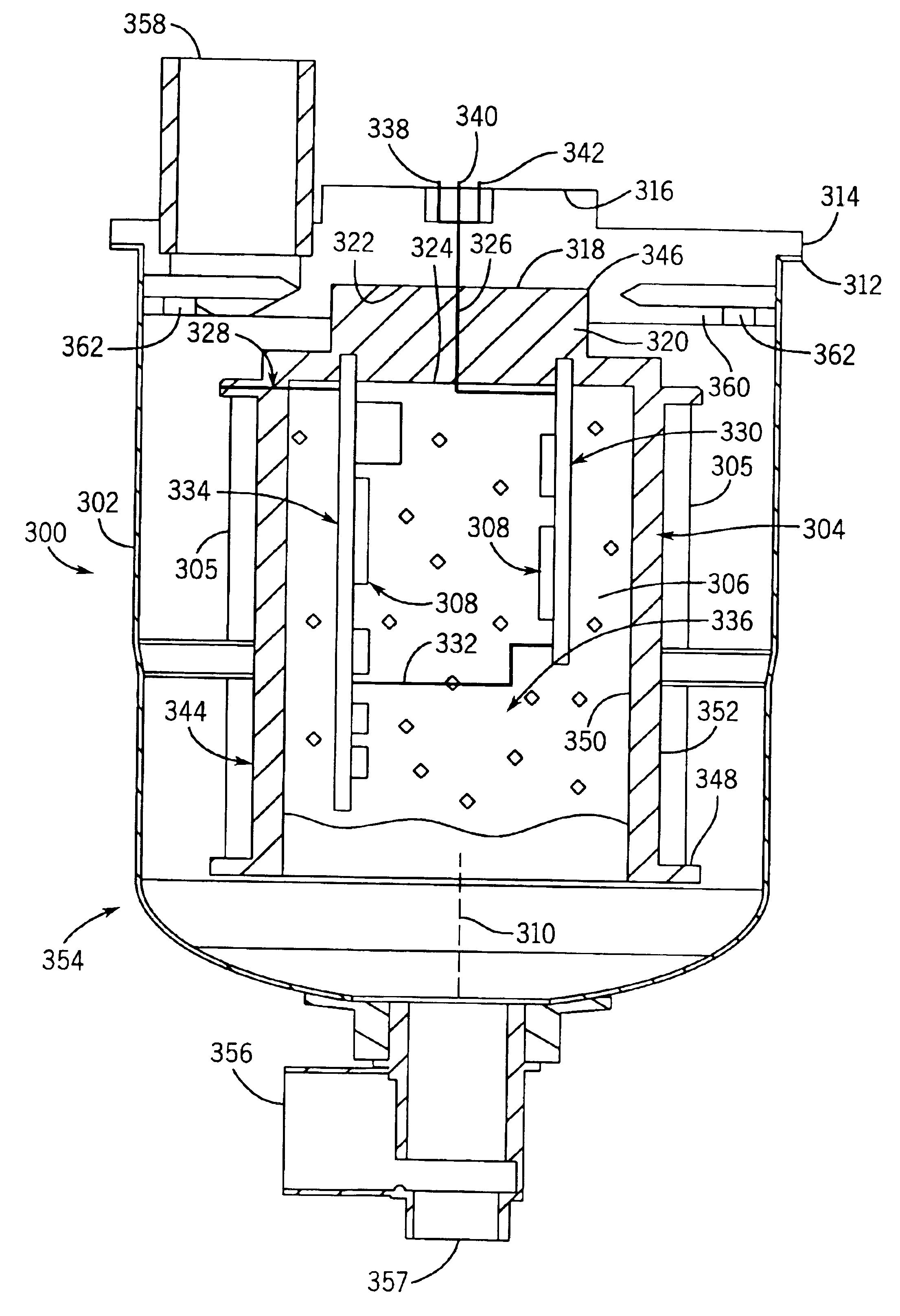
[0005]The present invention eliminates the need for the noted high voltage pass-through of a high voltage lead through the noted insulator. In the present invention, the high voltage power supply is disposed internally of such insulator, and in the preferred embodiment is in the hollow interior of the corona discharge electrode assembly. This eliminates the need for any external high voltage cables or connections and eliminates the need for the high voltage pass-through of a high voltage lead through the insulator.

Problems solved by technology

The insulator may also be heated to prevent moisture and contaminant accumulation on the insulating surface, thereby reducing the insulating properties of such section.

Method used


Image

  • Electrostatic precipitator with internal power supply
  • Electrostatic precipitator with internal power supply
  • Electrostatic precipitator with internal power supply

Examples


Embodiment Construction

U.S. Pat. No. 6,221,136

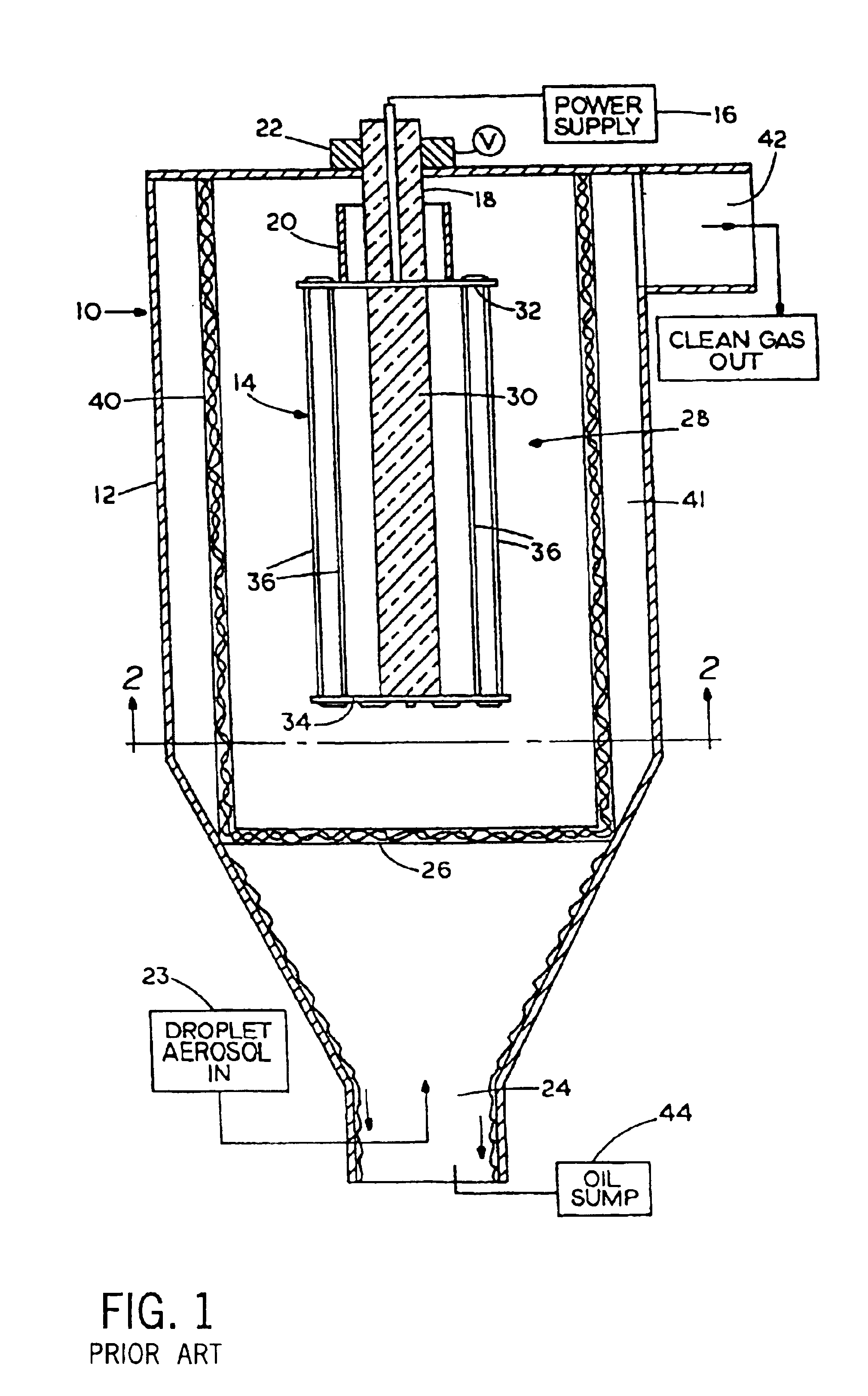
[0028]FIG. 1 is a schematic cross-sectional view of an electrostatic precipitator 10 made according to the invention of the '136 patent. A housing 12 has a discharging electrode assembly 14 to produce the corona discharge. The high voltage DC power supply 16 applies a high voltage (several thousand volts), to the electrode assembly 14 on a wire surrounded by an insulator bushing 18. The bushing 18 is surrounded by a high voltage shield 20, made of suitable conducting material.

[0029]An electric heater 22 is in contact with the insulator bushing 18 to keep the insulator bushing at a sufficiently high temperature to prevent vapor condensation and particle deposition on the bushing 18.

[0030]Gas containing suspended droplets and other particulate matter from a source 23 is directed to flow through an inlet opening 24 of the housing 12 and passes through a porous medium 26 in the inlet. The porous medium 26 is a relatively inefficient droplet collector to keep out l...


PUM

PropertyMeasurementUnit
DC voltageaaaaaaaaaa
voltageaaaaaaaaaa

Abstract

An electrostatic precipitator, including for a diesel engine electrostatic crankcase ventilation system for blowby gas, includes a corona discharge electrode assembly in a housing, an insulator extending along an internal surface of a wall of the housing, a power supply in the housing on the opposite side of the insulator from the housing wall such that the insulator is between the housing wall and the power supply, and a low voltage lead extending through the housing wall and through the insulator to the power supply, eliminating pass-through of a high voltage lead through the housing wall and through the insulator. The power supply is preferably provided in the hollow interior of the corona discharge electrode assembly.

Description

BACKGROUND AND SUMMARY[0001]The invention relates to electrostatic precipitators, including for diesel engine electrostatic crankcase ventilation systems for blowby gas for removing suspended particulate matter including oil droplets from the blowby gas.[0002]Electrostatic precipitators, including for diesel engine electrostatic crankcase ventilation systems, are known in the prior art. In its simplest form, a high voltage corona discharge electrode is placed in the center of a grounded tube or canister providing an annular ground plane around the electrode. A high DC voltage, such as several thousand volts, e.g. 15 kV, on the center discharge electrode causes a corona discharge to develop between the discharge electrode and the interior surface of the tube providing a collector electrode. As the gas containing suspended particles flows between the discharge electrode and the collector electrode provided by the wall of the tube, the particles are electrically charged by the corona i...

Claims


Application Information

Patent Timeline
Patent Type & Authority Patents(United States)
IPC IPC(8): B03C3/68B03C3/49B03C3/45B03C3/66F01M13/04
CPCB03C3/49B03C3/68F01M2013/0466B03C2201/30
Inventor HECKEL, SCOTT P.HOVERSON, GREGORYLIU, BENJAMIN Y. H.
Owner CUMMINS FILTRATION INC
Learn More