Sensor array for measuring plasma characteristics in plasma processing environments

a plasma processing environment and sensor array technology, applied in the field of plasma processing systems, can solve the problems of affecting the effect of plasma processing materials, affecting the usefulness of real-time plasma conditions, and affecting the effect of plasma processing,

Inactive Publication Date: 2005-06-07
KLA CORP
View PDF22 Cites 144 Cited by
  • Summary
  • Abstract
  • Description
  • Claims
  • Application Information

AI Technical Summary

Problems solved by technology

All of the techniques described above have limitations that restrict their usefulness in obtaining real-time measurements of plasma conditions within commercial plasma processing systems.
Many of these measuring devices are intrusive in that they require the use of a probe that protrudes into the plasma body, which inherently disrupts the plasma properties when processing materials.
Moreover, the use of any single-ended probe is intrusive, particularly when the probe is forward biased at or near the plasma potential, resulting in a condition that necessarily disrupts the electrical structure of the plasma body during processing.
Many of the techniques described are intended for experimental characterization of non-corrosive or non-depositing plasmas, and are thus not intended to collect plasma measurements under commercial processing conditions.
Finally, these teachings typically provide only a single-point approach to monitoring the plasma properties, and as such provide no means of determining the global or spatial properties of the processing plasma at its boundary.

Method used


Image

  • Sensor array for measuring plasma characteristics in plasma processing environments
  • Sensor array for measuring plasma characteristics in plasma processing environments
  • Sensor array for measuring plasma characteristics in plasma processing environments

Examples


Embodiment Construction

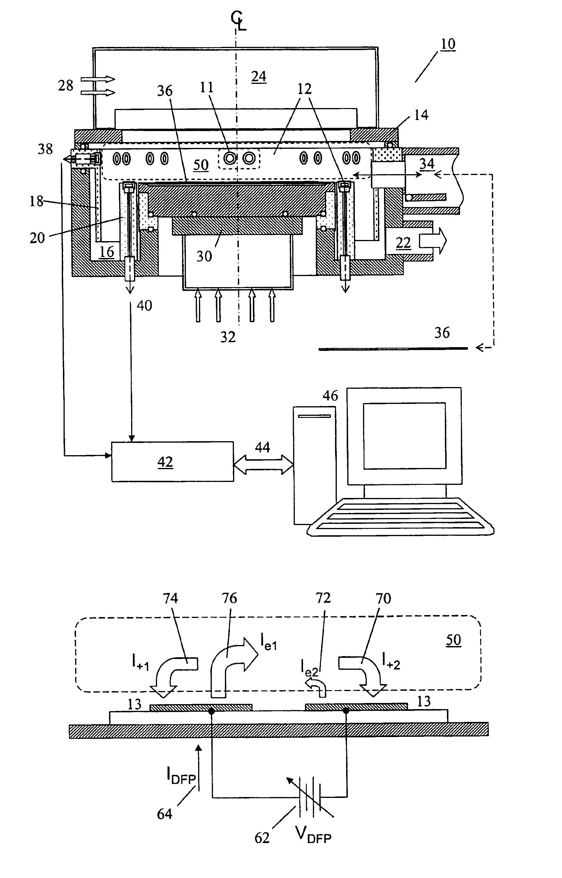
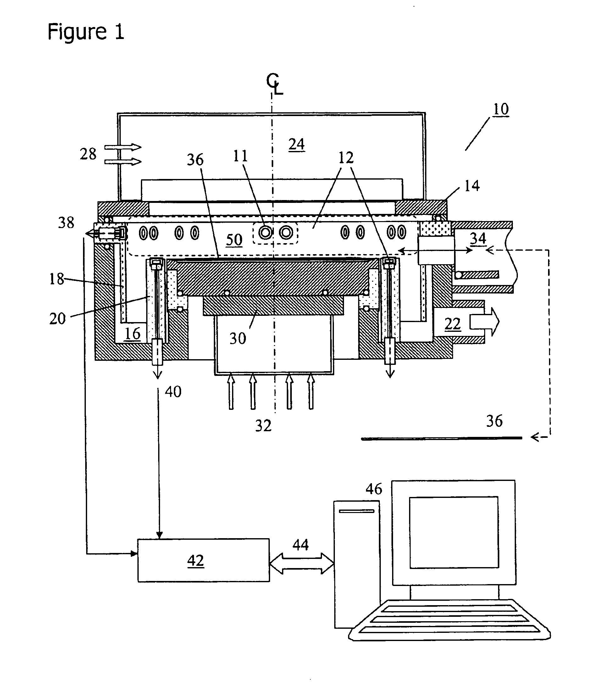
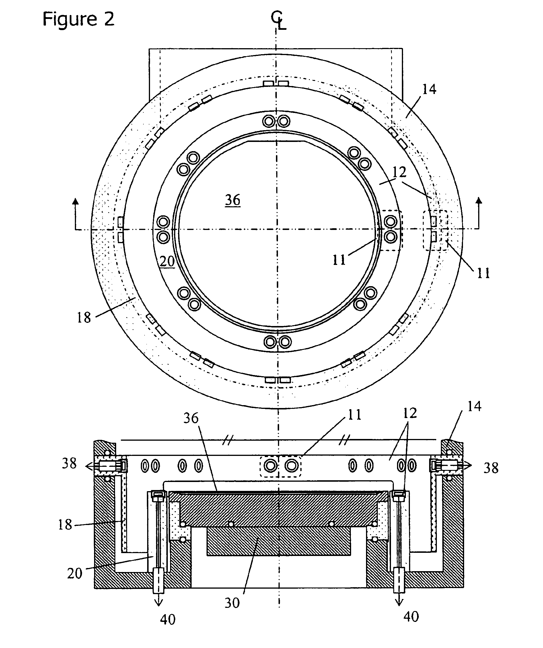
[0031]FIG. 1 illustrates one embodiment of an apparatus 10 that is capable of making real-time measurements of incident plasma current fluxes through arrays 12 of dual floating Langmuir probe (DFP) sensors 11 about the internal boundaries of a plasma processing system 14. In this particular illustration, two sensor arrays 12 are shown, with one array of DFP sensors disposed along the chamber liner 18, and a second array of DFP sensors disposed along the so-called “focus ring” or dielectric isolation ring 20. The processing system is 14 comprised of a vacuum processing chamber 16, a pumping manifold 22, a plasma source 24 mounted to the top of or in communication with the vacuum chamber 16, a gas delivery manifold or gas shroud (not shown), gas flow, thermal management and power services 28 connecting to the plasma source and system, and a wafer or workpiece chuck or mounting stage 30. In the case of a semiconductor processing system, the workpiece chuck may include a clamping means,...


PUM

PropertyMeasurementUnit
pressureaaaaaaaaaa
areaaaaaaaaaaa
ion saturation current densitiesaaaaaaaaaa

Abstract

A plasma processing system is provided with diagnostic apparatus for making in-situ measurements of plasma properties. The diagnostic apparatus generally comprises a non-invasive sensor array disposed within a plasma processing chamber, an electrical circuit for stimulating the sensors, and means for recording and communicating sensor measurements for monitoring or control of the plasma process. In one form, the sensors are dynamically pulsed dual floating Langmuir probes that measure incident charged particle currents and electron temperatures in proximity to the plasma boundary or boundaries within the processing system. The plasma measurements may be used to monitor the condition of the processing plasma or furnished to a process system controller for use in controlling the plasma process.

Description

BACKGROUND OF THE INVENTION[0001]1. Field of the Invention[0002]This invention relates generally to plasma processing systems, and more particularly to apparatus and methods for making in-situ measurements of plasma properties in plasma processing systems.[0003]2. Brief Description of the Prior Art[0004]Single-ended Langmuir probes and other diagnostic probe methods have been widely used in industry to characterize plasmas, and more specifically plasmas used in low pressure vacuum processing systems. Measurement techniques have been described in reference books including Swift and Schwar, Electric Probes for Plasma Diagnostics, (American Elsevier, New York, 1969) and by Hershkowitz in Plasma Diagnostic, Vol. 1, Discharge Parameters and Chemistry, ed. Aucciello and Flamm (Academic, New York, 1989), pp. 113-183. The use of single-ended Langmuir probe diagnostic methods for monitoring plasma processing environments is also known, along with methods for operating the probes as generally...

Claims


Application Information

Patent Timeline
Patent Type & Authority Patents(United States)
IPC IPC(8): C23C16/00C23F1/00G01N27/60G01R27/26G01K11/00G01R27/00G01R27/28H01L21/00H01L21/02H01L21/302H01L21/461H01L21/306H05H1/00H01JH01J37/32
CPCH01J37/32954H01J37/32935H01L21/3065H01L21/02
Inventor MAHONEY, LEONARD J.ALMGREN, CARL W.ROCHE, GREGORY A.SAYLOR, WILLIAM W.SPROUL, WILLIAM D.WALDE, HENDRIK V.
Owner KLA CORP
Why Eureka
Try Eureka