Fuel cell system with mixer/eductor

a fuel cell and mixer technology, applied in the field of fuel cells, can solve the problems of increasing the cost and reliability of a commercial system, the overall complexity of the system hardware, and the cost and reliability of the recycle blower, so as to reduce the differential pressure and reduce the difference in pressure

Inactive Publication Date: 2005-06-07
FUELCELL ENERGY INC
View PDF4 Cites 23 Cited by
  • Summary
  • Abstract
  • Description
  • Claims
  • Application Information

AI Technical Summary

Benefits of technology

[0012]In accordance with the principles of the present invention, the above and other objectives are realized in a fuel cell system of the above-type in which a mixer / eductor is utilized in the system. The mixer / eductor receives the fresh oxidant or air to be fed to the inlet at the cathode-side of the stack and also receives the exhaust gas delivered from the exit of the anode-side of the stack. The mixer / eductor operates on and mixes these gases for passage through an oxidizer and subsequent delivery to the inlet at the cathode-side of the stack. In accord with the invention, the eductor / mixer operates on and mixes these gases such that the pressure difference between the gas at the exit of the anode-side of the stack and the gas at the inlet of the cathode-side of the stack is reduced. Also, additional control over the reduction of the difference in pressure is realized by controlling the flow rate of the supplied fresh air.
[0013]In a further aspect of the invention, a recycle blower is placed between the exit at the cathode-side of the stack and the mixer / eductor to provide additional control in reducing the differential pressure.

Problems solved by technology

This has the advantage of independently controlling the pressure balance but adds significant cost and reliability issues to a commercial system.
Disadvantages to this system are, again, the cost and reliability of the recycle blower as well as the overall complexity of the system hardware.
The experience in this case is that a multitude of operating problems can arise.
Problems include non-uniform stack temperatures, reduced system efficiency and elevated exhaust pollutant emissions.

Method used


Image

  • Fuel cell system with mixer/eductor
  • Fuel cell system with mixer/eductor
  • Fuel cell system with mixer/eductor

Examples


Embodiment Construction

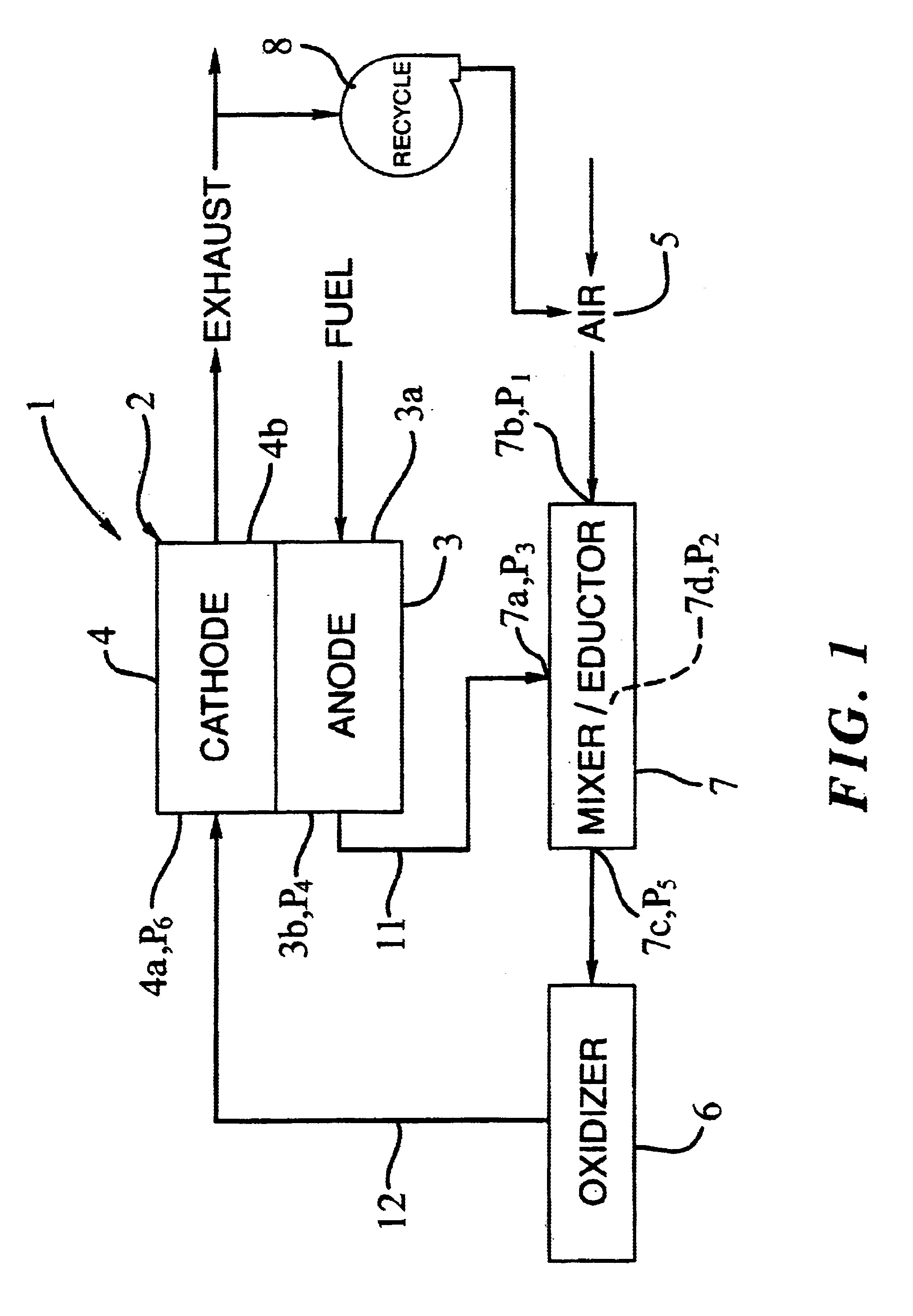
[0021]FIG. 1 shows schematically a fuel cell system 1 in accordance with the principles of the present invention. As shown, the system 1 includes a fuel cell stack 2 having a fuel or anode-side 3 and an oxidant or cathode-side 4. The anode-side 3 includes an inlet 3a for supply of fresh fuel and an exit 3b for extraction of exhausted fuel. The cathode-side 4 also includes an inlet 4a for receiving oxidant and an exit 4b for expelling exhausted oxidant.

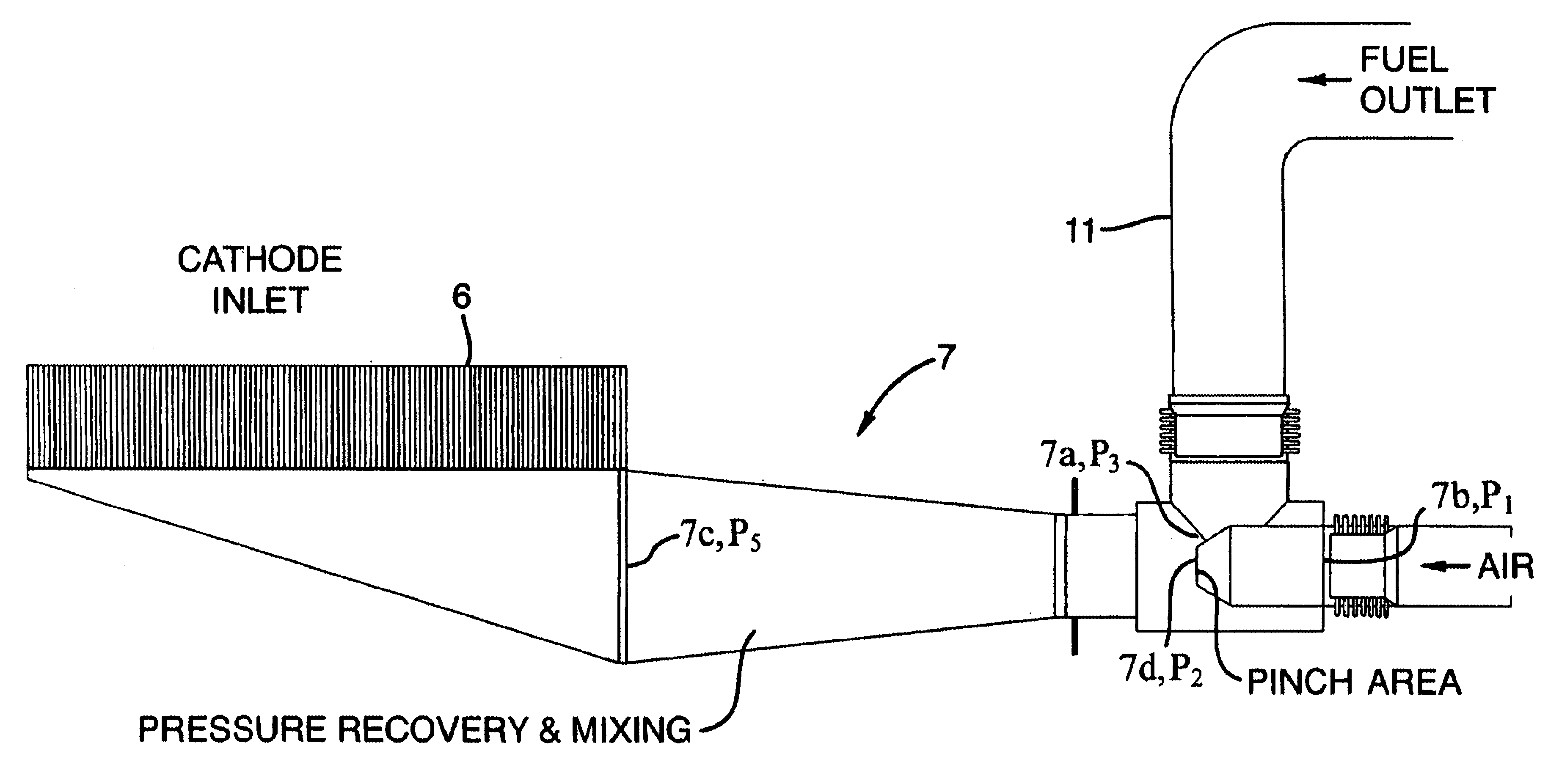
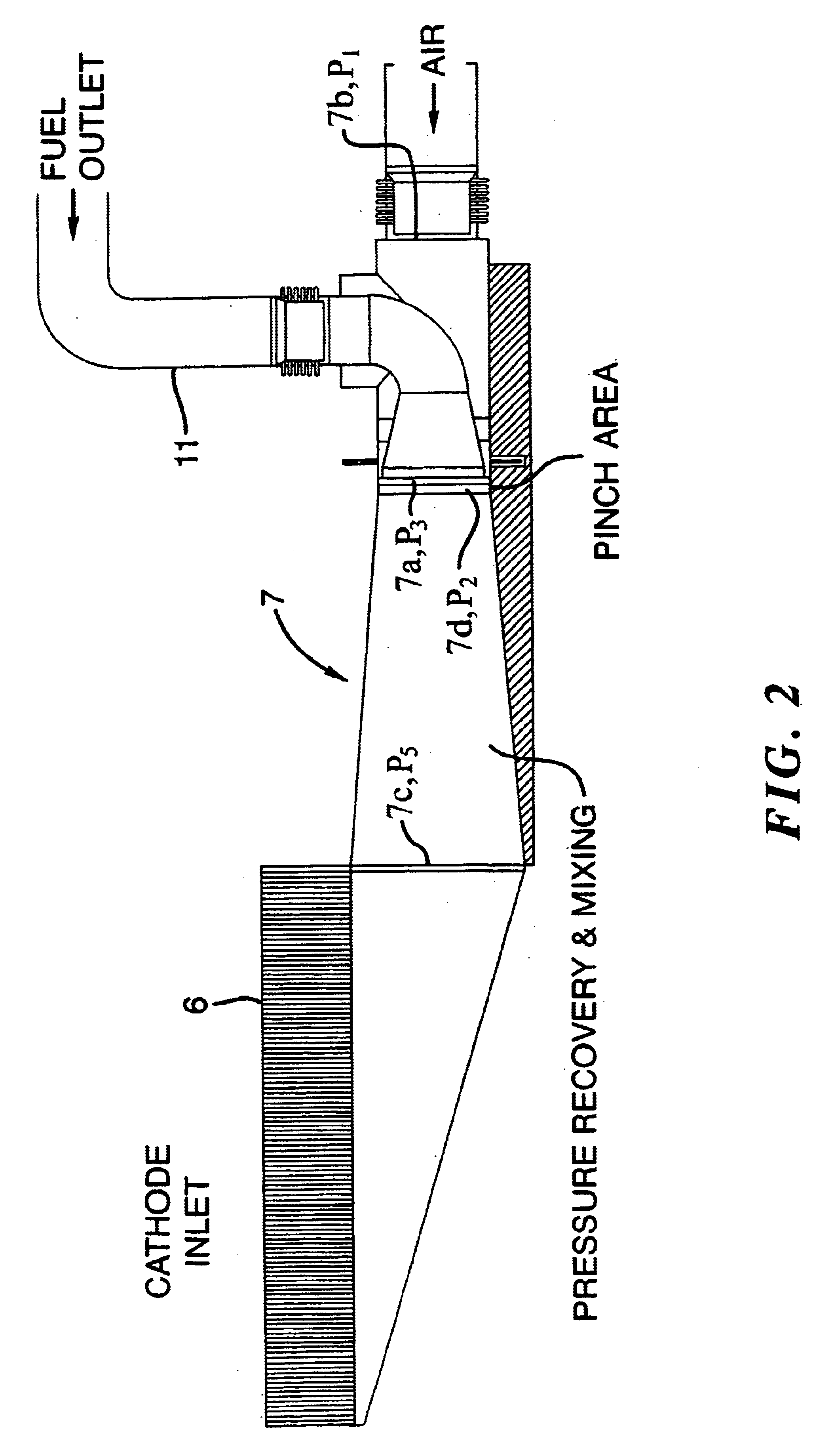
[0022]An oxidant source 5 supplies oxidant, shown as air, at a controllable flow rate or velocity to the system 1. The oxidant is heated by burning the oxidant in an oxidizer 6 with exhausted fuel carried by piping 11 from the exit 3b of the anode-side 3 of the stack 2. The oxidizer 6 is typically an oxidation catalyst bed. The resultant heated gas is supplied via piping 12 to the inlet 4a of the cathode-side 4 of the stack 2.

[0023]In order to keep the difference in pressure between the oxidant and fuel gases passing through the stack ...


PUM

PropertyMeasurementUnit
pressureaaaaaaaaaa
velocityaaaaaaaaaa
pressure differenceaaaaaaaaaa

Abstract

A fuel cell system containing a mixer / eductor for reducing the pressure difference between the gases in the anode and cathode-sides of a fuel cell stack. The mixer / eductor is placed at the mixing point between the anode tail or exhaust fuel gas and the fresh air or oxidant supply gas inlet. The incoming oxidant pressure is converted to a high momentum stream to form a suction on the fuel exhaust gas. This suction compensates for pressure losses in the gas piping and the oxidizer used to burn the exhaust fuel gas resulting in substantial balancing of the anode and cathode-side gas pressures. The mixer / eductor can be in the form of an axial or annular jet pump unit, both of which are advantageous in aggressively mixing the fuel exhaust gas with the incoming oxidant or air. The mixer / eductor geometry can be varied to provide the proper suction to balance pressures over a chosen range of operating conditions. Additionally, the incoming fresh air flow rate or an oxidant exhaust recycle flow rate can be varied to actively balance pressures at any operating point.

Description

BACKGROUND OF THE INVENTION[0001]1. Field of the Invention[0002]This invention relates to fuel cell systems employing fuel cell stacks having a pressure differential between the anode or fuel and cathode or oxidant sides of the stack and, in particular, to fuel cell systems of this type incorporating mechanisms for lessening this pressure differential.[0003]2. Description of the Related Art[0004]A fuel cell is a device which directly converts chemical energy stored in a fuel such as hydrogen or methane into electrical energy by means of an electrochemical reaction. This differs from traditional electric power generating methods which must first combust the fuel to produce heat and then convert the heat into mechanical energy and finally into electricity. The more direct conversion process employed by a fuel cell has significant advantages over traditional means in both increased efficiency and reduced pollutant emissions.[0005]In general, a fuel cell, similar to a battery, includes ...

Claims


Application Information

Patent Timeline
Patent Type & Authority Patents(United States)
IPC IPC(8): H01M2/00H01M2/14H01M2/02H01M8/12H01M8/04H01M8/06H01M8/24
CPCH01M8/04104H01M8/2425H01M8/04097Y02E60/50H01M8/0662H01M8/04089
Inventor BLANCHET, SCOTTPATEL, PINAKIN
Owner FUELCELL ENERGY INC
Why Eureka
Try Eureka