Stator assembly with an overmolding that secures magnets to a flux ring and the flux ring to a stator housing

a stator assembly and overmolding technology, applied in the direction of magnetic circuit rotating parts, portable power-driven tools, magnetic circuit shape/form/construction, etc., can solve the problems of electric motors that cannot properly function, movement of magnets within the stator assembly, and electric motors that cannot. achieve the effect of preventing the collapse of the flux ring

Inactive Publication Date: 2005-06-07
BLACK & DECKER INC
View PDF159 Cites 53 Cited by
  • Summary
  • Abstract
  • Description
  • Claims
  • Application Information

AI Technical Summary

Benefits of technology

[0006]Accordingly, the present invention provides a stator assembly for an electric motor. The stator assembly includes a stator housing, a split flux ring inserted into the stator housing and a plurality of magnets on an inner surface of the flux ring. An overmolding secures the magnets to the flux ring and asserts a radial force on the flux ring to secure it to the stator housing. Additionally, the overmolding fills the seam of the flux ring and prevents collapse of the flux ring.

Problems solved by technology

It is possible that a sudden shock to the electric motor will destroy the bond between the magnet and the flux ring or stator housing.
This would result in movement of the magnet within the stator assembly.
As a result, the electric motor ceases to properly function.
However, a disadvantage of the anchoring systems described in the above-identified patent applications is that they require the use of injection molded magnetic material.
This is typically the most expensive type of magnetic material per unit flux.

Method used


Image

  • Stator assembly with an overmolding that secures magnets to a flux ring and the flux ring to a stator housing
  • Stator assembly with an overmolding that secures magnets to a flux ring and the flux ring to a stator housing
  • Stator assembly with an overmolding that secures magnets to a flux ring and the flux ring to a stator housing

Examples


Embodiment Construction

[0028]The following description of the preferred embodiments is merely exemplary in nature and is in no way intended to limit the invention, its application, or uses.

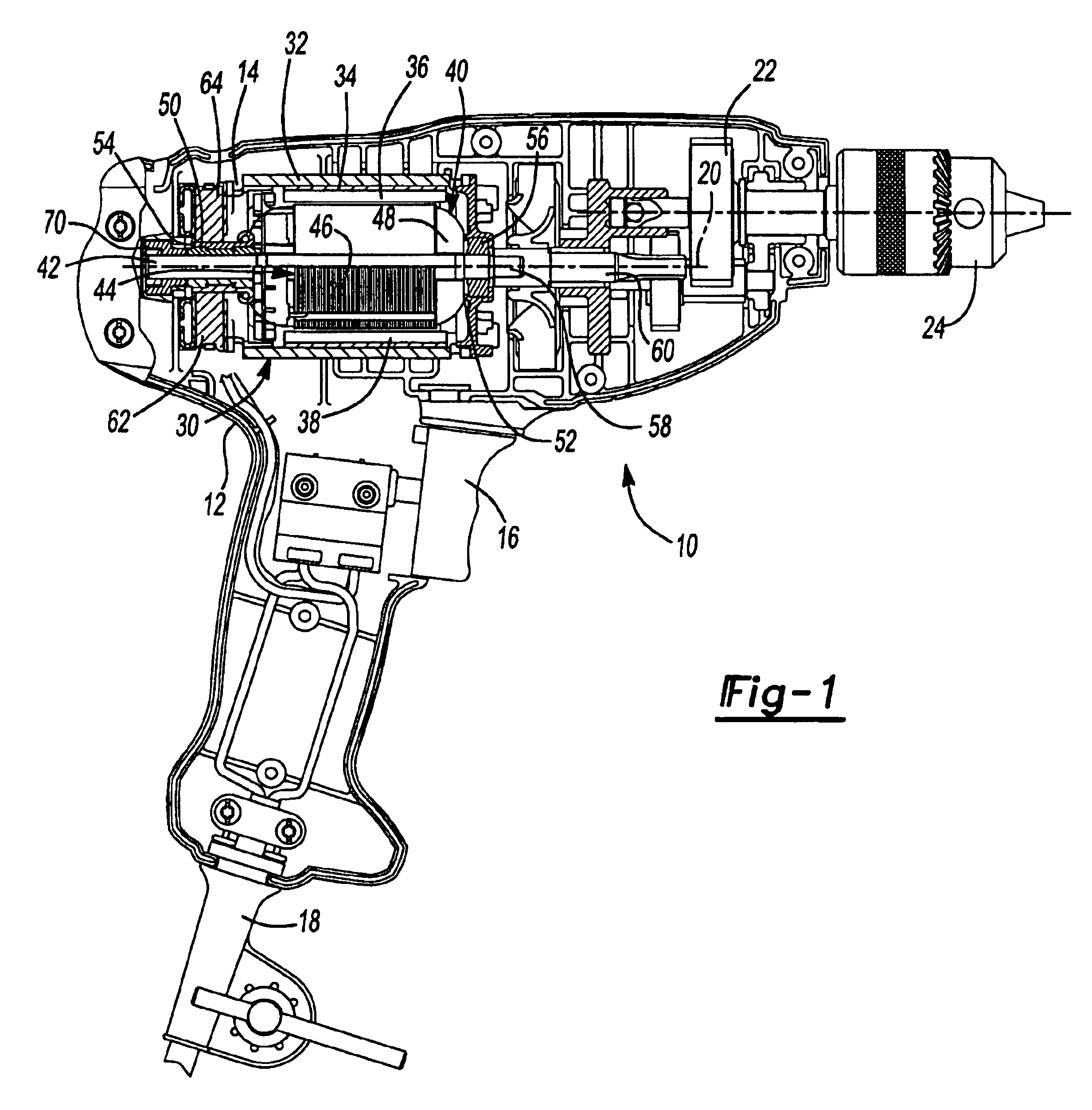
[0029]Referring now to FIG. 1, a power tool 10 is shown. The power tool 10 is illustrated as a drill, however, any type of power tool may be used in accordance with the present invention. The power tool 10 includes a housing 12 which surrounds a motor 14. An activation member 16 is coupled with the motor and a power source 18. The power source 18 includes either a power cord (AC current) or includes a battery (DC current) (not shown). The motor 14 is coupled with an output 20 that includes a transmission 22 and a chuck 24. The chuck 24 is operable to retain a tool (not shown).

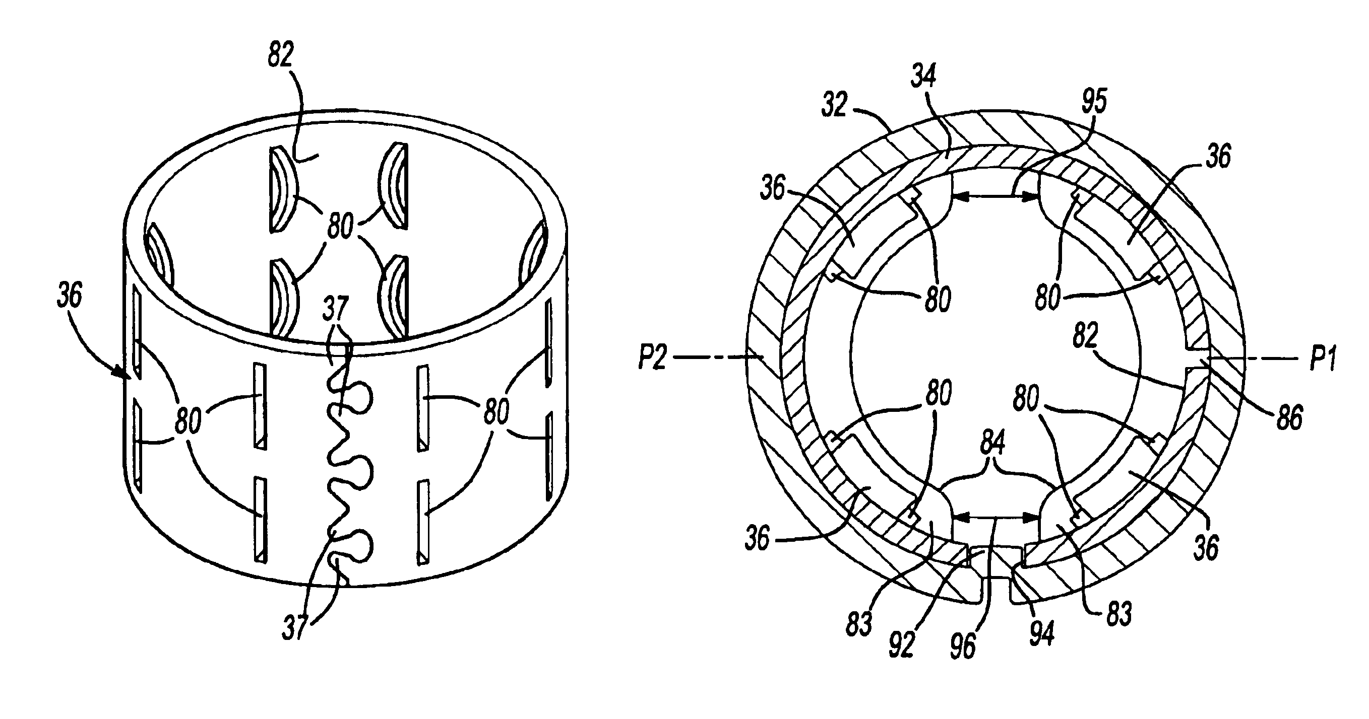
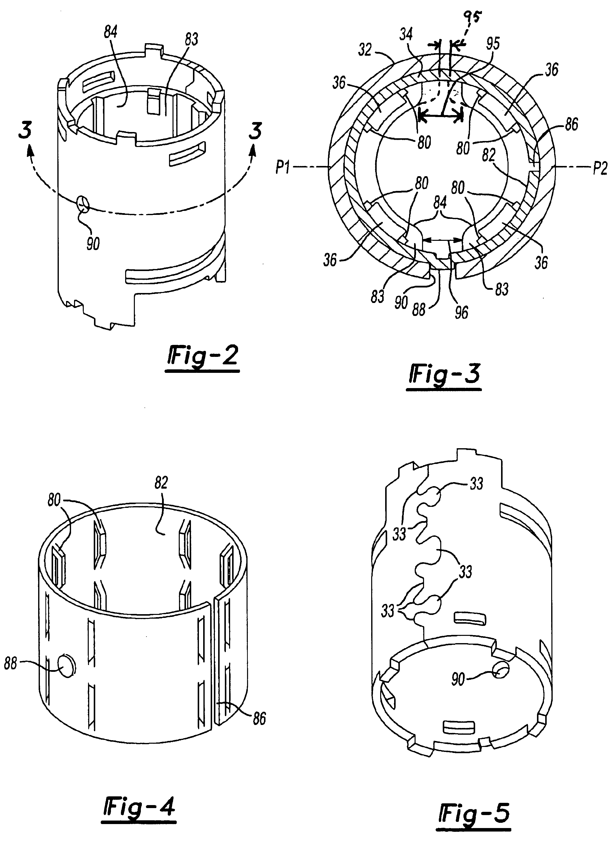
[0030]The motor includes a stator assembly 30. The stator assembly 30 includes a stator housing 32, a flux ring 34 and magnets 36. The flux ring 34 is an expandable or split flux ring. An armature 40 includes a shaft 42, a rotor 44 and a commutator...


PUM

PropertyMeasurementUnit
widthsaaaaaaaaaa
magnetic poleaaaaaaaaaa
magneticaaaaaaaaaa

Abstract

A stator assembly for an electric motor includes a stator housing, an expandable flux ring inserted into the stator housing and a plurality of magnets on an inner surface of the flux ring. Overmold material is molded around the magnets in the flux ring, such as by injection molding. The pressure of the overmold material as it is being molded expands the flux ring pressing the flux ring into engagement with the stator housing. The overmold material secures the magnets to the flux ring and the flux ring to the housing. One of the flux ring and stator housing has a dimple that engages a hole in the other of the flux ring and stator housing to align the flux ring and stator housing. In an aspect, the overmold material is molded to form at least one of a commutator end or rear bearing support, front bearing support and fan baffle. In an aspect, the overmold material is molded to form a keying feature. The keying feature can be slots of different widths between magnetic poles of the stator assembly. In an aspect, the flux ring and housing are preformed as a unit by stamping them from blanks and rolling them together. In a variation, the flux ring blank is rolled first to form the flux ring and the housing blank rolled around the flux ring with the flux ring acting as a rolling arbor.

Description

CROSS-REFERENCE TO RELATED APPLICATIONS[0001]This application is a continuation-in-part of U.S. patent application Ser. No. 10 / 468,643 filed Aug. 20, 2003, which is a § 371 National Phase filing of PCT International Application PCT / US02 / 05029 filed Feb. 22, 2002 (International Publication Number WO 02 / 068235 A2) which claims the benefit of U.S. Provisional Application No. 60 / 271,141 filed Feb. 23, 2001. This application claims the benefit of U.S. Provisional Application No. 60 / 433,496 filed Dec. 13, 2002. The disclosures of the above applications are incorporated herein by reference.FIELD OF THE INVENTION[0002]The present invention relates to electric motors, and more particularly to stator assemblies for electric motors.BACKGROUND OF THE INVENTION[0003]In the construction of stator assemblies for permanent magnet electric motors, magnets are retained within the stator assembly. For example, in a brush-type permanent magnet electric motor, magnets are retained on a stator housing or...

Claims


Application Information

Patent Timeline
Patent Type & Authority Patents(United States)
IPC IPC(8): H02K5/08H02K5/173H02K5/00H02K7/14H02K1/27H02K1/12H02K1/17H02K23/02H02K23/04H02K9/06H02K9/04
CPCH02K1/17H02K1/2786H02K5/00H02K5/08H02K5/1735H02K23/04H02K7/145Y10T29/49009H02K9/06Y10T29/49075Y10T29/49012B25F5/008H02K1/2791H02K1/18H02K5/16H02K15/03
Inventor ORTT, EARL M.AGNES, MICHAEL J.DU, HUNG
Owner BLACK & DECKER INC
Why Eureka
Try Eureka