

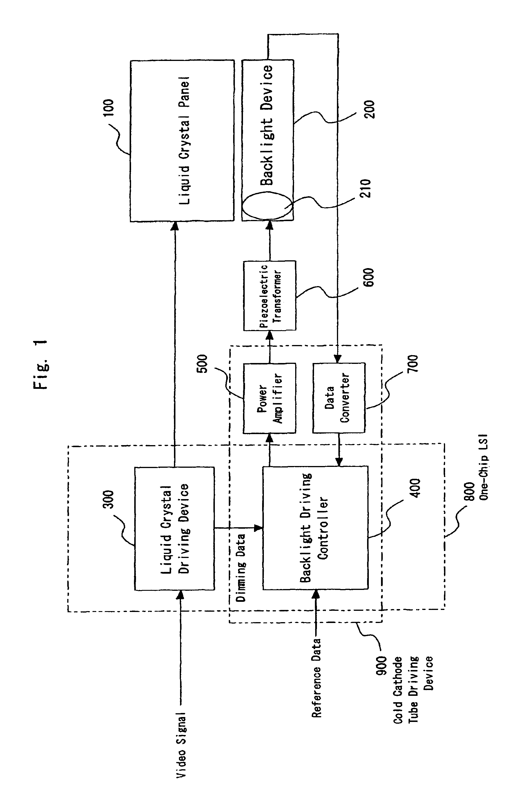
Cold-cathode driver and liquid crystal display
a technology of liquid crystal display and cold cathode, which is applied in the direction of device details, instruments, and device details of piezoelectric/electrostrictive devices, etc., can solve the problem that the current at on-time cannot be controlled to be constan
- Summary
- Abstract
- Description
- Claims
- Application Information
AI Technical Summary
Benefits of technology
Problems solved by technology
Method used
Image

Examples
embodiment 1
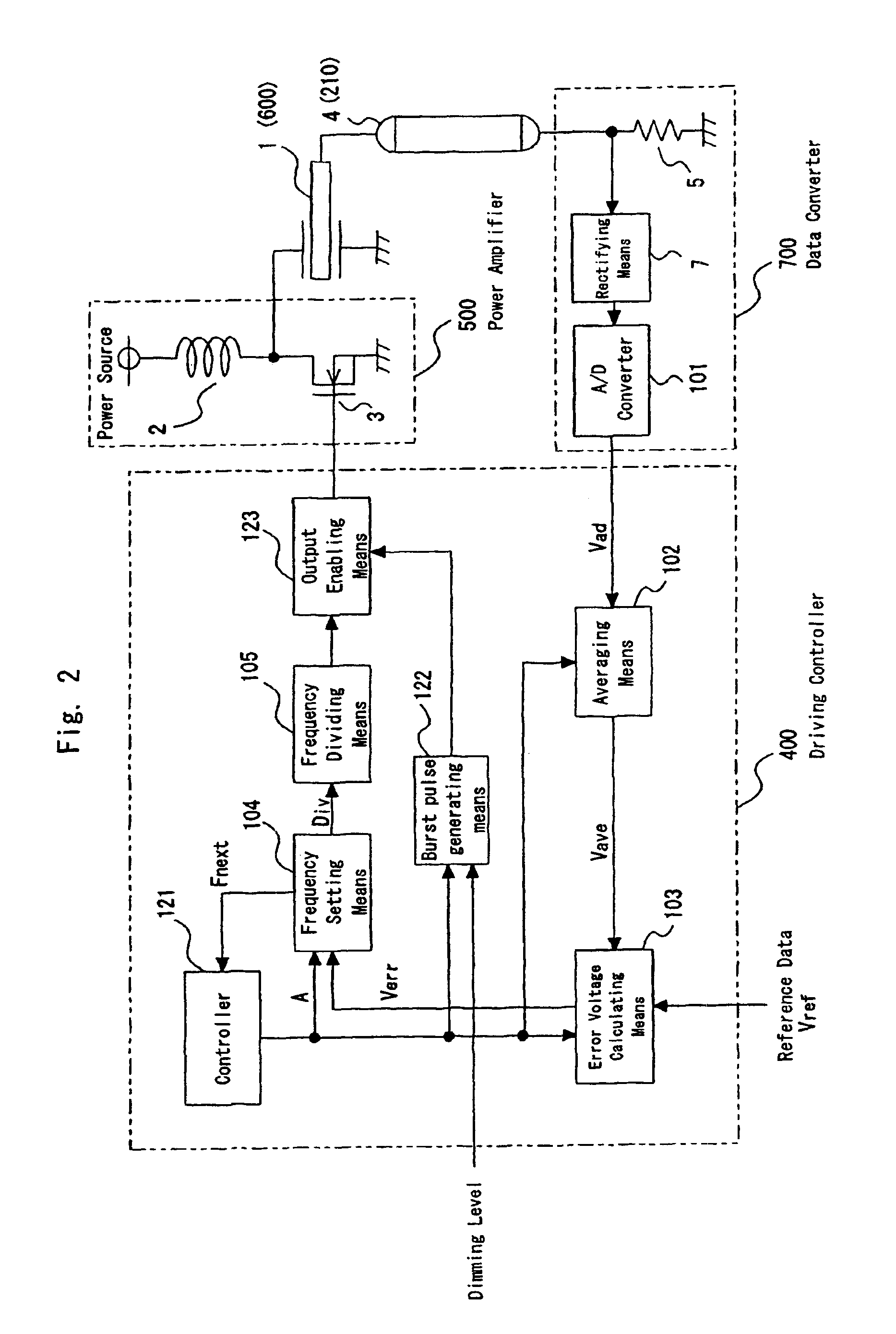
[0171]FIG. 2 is a block diagram showing a configuration of the cold cathode tube driving device 900 in the liquid crystal display device according to the embodiment 1 of the invention. In FIG. 2, numeral 1 denotes a piezoelectric transformer (corresponding to the piezoelectric transformer 600 in FIG. 1), 2 a coil, 3 a switching transistor (FET), 4 a cold cathode tube (corresponding to the cold cathode tube 210), 5 a current detector that detects current flowing through the cold cathode tube 4 and converts the detected result into a voltage signal, 7 a rectifying means (e.g., a peak detector circuit) that rectifies a sinusoidal voltage signal taken out from the current detector 5 and converts the resultant into DC voltage and 101 an A / D converter that converts the voltage outputted from the rectifying means 7 into a digital signal. Although the current detector 5 is typically represented by a mark of a resistance in the figure, it is not limited to the resistance. The A / D converter 1...
embodiment 2
[0190]Subsequently explained is a cold cathode tube driving device according to the embodiment 2 of the invention. In order to correctly detect the average current flowing through the cold cathode tube 4, the detection range for a minimum of one distribution cycle is required. In the embodiment 1, the burst pulse width is required to be greater than the distribution cycle and there is a restriction for the lower limit of the dimming level. The embodiment 2 solves this subject.
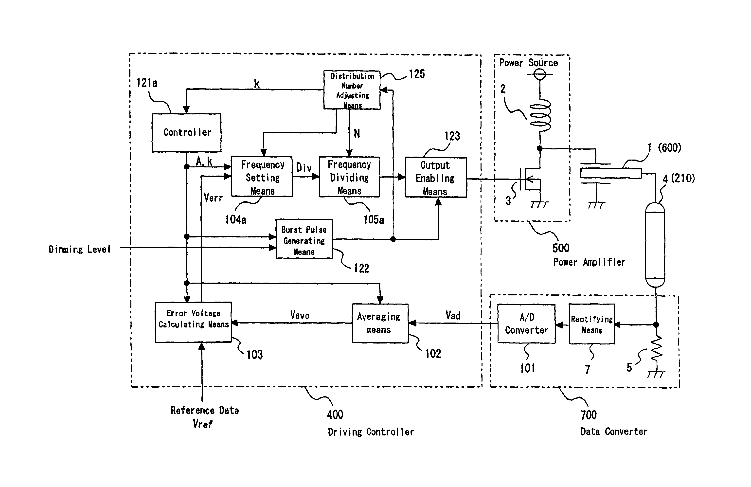
[0191]FIG. 9 is a block diagram showing a configuration of a cold cathode tube driving device according to the embodiment 2. Numeral 104a denotes a frequency setting means for setting a frequency of a driving pulse of the piezoelectric transformer 1. This frequency setting means 104a adds or subtracts the frequency corresponding to the error data Verr to or from the previous frequency setting value Fprev, and outputs M-bit data Fnext. The different point from the frequency setting means 104 explained in the emb...
embodiment 3
[0202]Subsequently, a cold cathode tube driving device according to an embodiment 3 of the invention will be explained.
[0203]FIG. 13 shows a block diagram showing a configuration of the cold cathode tube driving device according to the embodiment 3 of the invention. This embodiment provides a cold cathode tube driving device that does not deteriorate a lighting performance and lighting quality at the starting even if the dimming level is low.
[0204]In FIG. 13, numeral 14 denotes voltage detecting means for detecting an output voltage from the piezoelectric transformer 1, and 15 a shielding means for turning on or off the detected voltage of the piezoelectric transformer 1 detected by the voltage detecting means 14. The shielding means is configured such that the output voltage therefrom becomes at “L” level when the detected voltage is turned off. Numeral 7a denotes a peak detecting means for detecting the output voltage of the piezoelectric transformer 1 outputted from the shielding...
PUM
 Abstract
Description
Claims
Application Information