
Data processing apparatus capable of communicating with output apparatus and its data processing method

Inactive Publication Date: 2005-06-07
CANON KK
View PDF3 Cites 5 Cited by
  • Summary
  • Abstract
  • Description
  • Claims
  • Application Information

AI Technical Summary

Benefits of technology

[0007]The invention is made to solve the above problems and it is an object of the invention to provide a data processing apparatus in which feature information which makes it possible to presume various print processing times in the case where a specific compression method is applied and the case where it is not applied is obtained, printer control commands are sequentially formed while a compression method whereby a relatively high-speed process can be performed is dynamically determined on the basis of the feature information, thereby enabling a relatively high-speed printing process to be realized. It is also an object of the invention to provide a data processing method for such a data processing apparatus and a memory medium in which a computer readable program has been stored.
[0021]According to the data processing method of the invention, the method comprises: a printer command forming step of constructing a print image by analyzing a drawing command which is formed by an operating system and forming a printer control command which is based on the print image and should be transferred to the printer; an obtaining step of obtaining feature information to presume print processing times by the printer command forming step in the case where a specific compression method is used and the case where it is not used; a discriminating step of discriminating whether the specific compression method should be used in the printer command forming step or not on the basis of the feature information obtained by the first obtaining step; and a deciding step of deciding the formation of the printer control command which is formed by the printer command forming step and to which the specific compression method is applied and the formation of the printer control command to which the specific compression method is not applied on the basis of a discrimination result of the discriminating step. Therefore, whether the compression method is applied to a print data amount which fluctuates or not can be dynamically determined in consideration of the feature information to presume the print processing time by the printer command forming step. For print data such that the presumed processing time is below the effect that will be obtained by the compression, the printer control command which is based on the print image and should be transferred to the printer is formed without actively compressing, and a series of printing processes can be remarkably reduced.

Problems solved by technology

In the printer driver according to the conventional technique, since a processing time that is required for various printing processes is not considered in a step of forming the printer control command while applying a specific compression method, there is a problem such that a relatively high-speed printing process cannot be performed.

Method used


Image

  • Data processing apparatus capable of communicating with output apparatus and its data processing method
  • Data processing apparatus capable of communicating with output apparatus and its data processing method
  • Data processing apparatus capable of communicating with output apparatus and its data processing method

Examples


first embodiment

[First Embodiment]

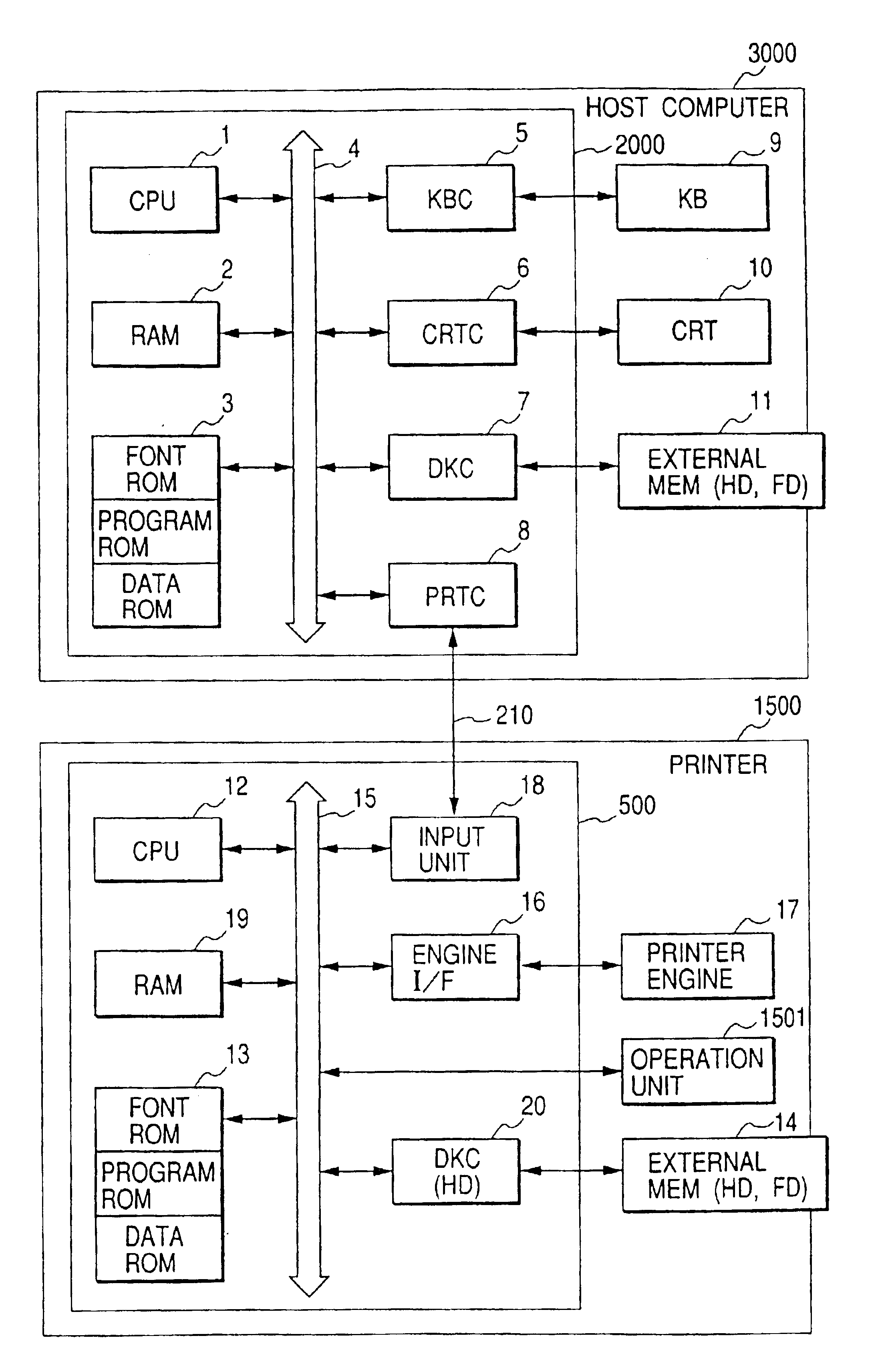
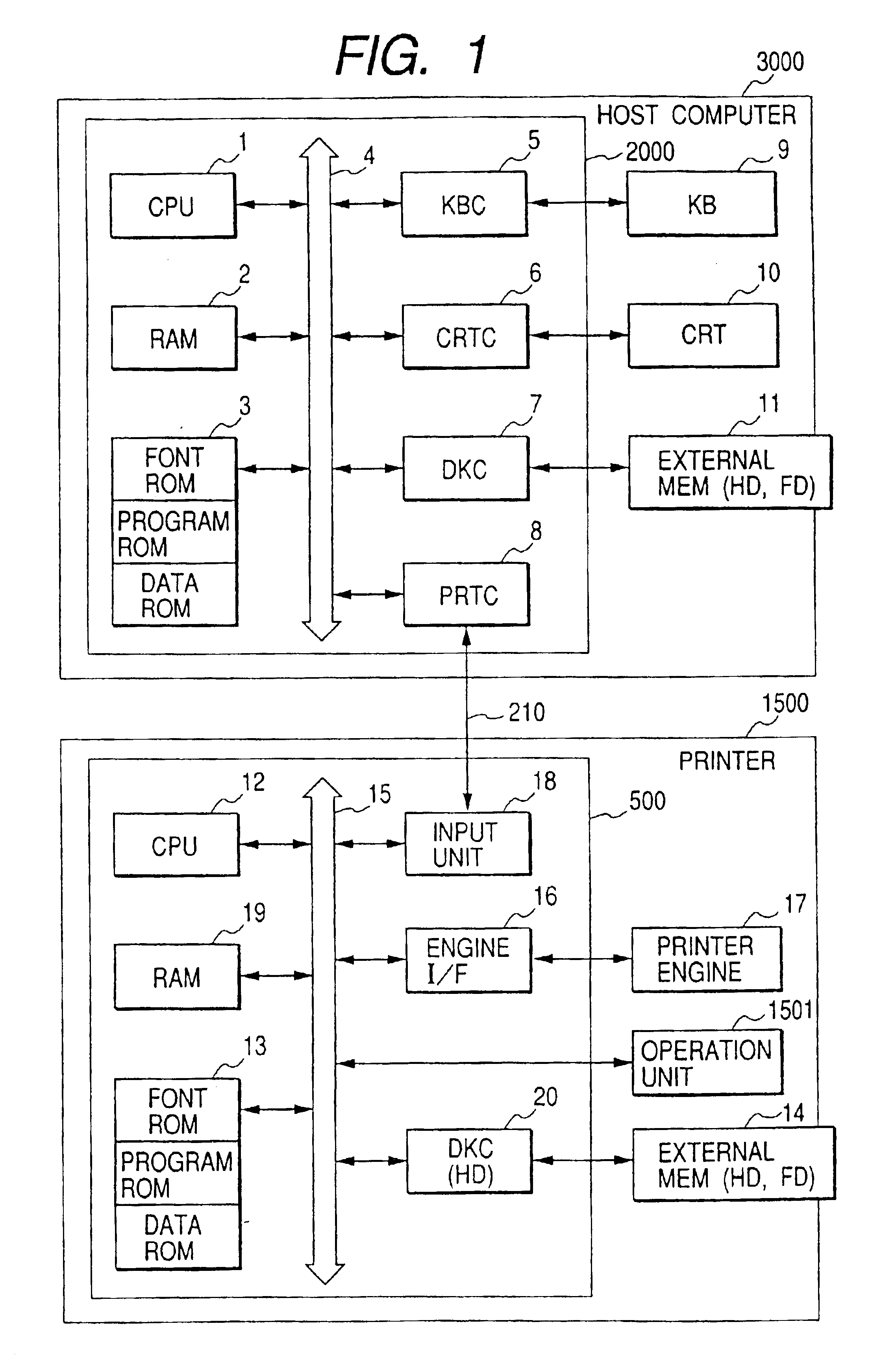
[0032]FIG. 1 is a block diagram for explaining a construction of a printing system to which a data processing apparatus showing the first embodiment of the invention can be applied. It will be obviously understood that the invention can be applied to any one of a single equipment, a system comprising a plurality of equipment, and a system which is connected through a network such as LAN, WAN, or the like and in which processes are executed so long as the functions of the invention are executed.

[0033]In the diagram, reference numeral 3000 denotes a host computer having a CPU 1 for executing a document process of a document in which figures, images, characters, tables (including a spreadsheet or the like), and the like mixedly exist on the basis of a document processing program or the like stored in a program ROM of an ROM 3. The CPU 1 collectively controls devices which are connected to a system bus 4.

[0034]An operating system program (hereinafter, abbreviated to an...

second embodiment

[Second Embodiment]

[0109]The above first embodiment has been described with respect to the case of determining whether the compression method A is performed or not by the equation (6) on the assumption that the memory size of the RAM 19 on the printer 1500 side is constant as a prerequisite. However, it is also possible to construct in a manner such that the printer driver which has been loaded into the RAM 2 of the host computer 3000 and is operating thereon obtains the hardware environment of the printer 1500 through the bidirectional interface, network, or the like and changes the feature information to enable the specific print processing time to be presumed in accordance with the environment. Such an embodiment will now be described hereinbelow.

[0110]In the embodiment, it is assumed that the constant values (γ1, γ2) as feature information which enables the processing time that is required for phase 5 (development of the printer control command in the printer) shown in the first...


PUM


Abstract

A data processing apparatus communicating with a printer through a predetermined communication medium, in which a printer command forming unit constructs a print image by analyzing a drawing command formed by an operating system and forms a printer control command based on the print image; a first obtaining unit obtains feature information to presume print processing times by the printer command forming unit where a specific compression method is used and where it is not used; a discriminating unit discriminates whether the printer command forming unit should use the specific compression method or not based on the feature information obtained by the first obtaining unit; and a controller switches and controls whether to apply the specific compression method in forming the printer command based on a discrimination result of the discriminating unit.

Description

[0001]This application is a division of application Ser. No. 09 / 208,976, filed Dec. 11, 1998, now U.S. Pat. No. 6,535,292.BACKGROUND OF THE INVENTION[0002]1. Field of the Invention[0003]The invention relates to a data processing apparatus which can communicate with a printer through a predetermined communication medium, a data processing method of the data processing apparatus, and a memory medium in which a computer readable program has been stored.[0004]2. Related Background Art[0005]Hitherto, in a printing system comprising a host computer and a printer connected to the host computer, a conventional printer driver (printer control command forming program) which operates on the host computer forms a printer control command while always applying a predetermined data compression method. In the case where a data compressing process cannot be performed due to some reasons or a compression effect cannot be obtained, another compression method in place of it is applied or a printer cont...

Claims


Application Information

Patent Timeline
IPC IPC(8): G06K15/00B41J5/30G06F3/12
CPCG06K15/00G06K15/1865G06K15/1861G06K2215/0011
Inventor KUROI, YOSHINOBU
Owner CANON KK
Learn More