Contact or transfer roller

a technology of contact or transfer roller, which is applied in the direction of printing presses, rotary presses, printing presses, etc., can solve the problems of high demands, inability to solve the above-mentioned problems, and inability to abrasion behavior and mechanical stability, etc., to achieve high surface tension, increase water balance and need, and low surface tension

Inactive Publication Date: 2011-02-24
WEROS TECH
View PDF8 Cites 2 Cited by
  • Summary
  • Abstract
  • Description
  • Claims
  • Application Information

AI Technical Summary

Benefits of technology

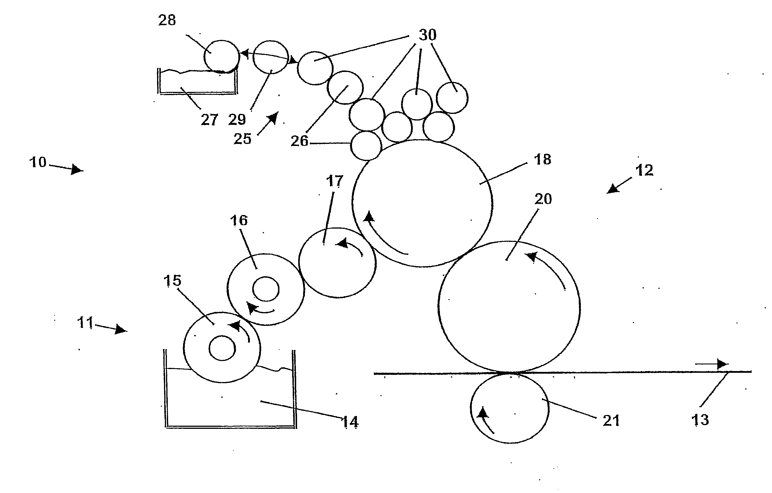
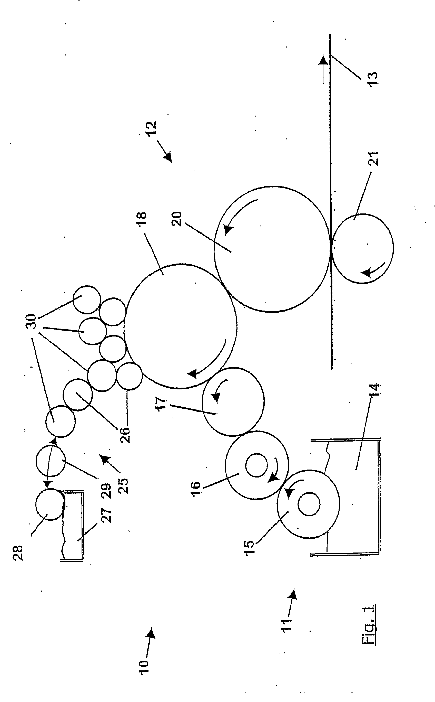
[0019]Accordingly, the inventive inking unit rollers having a low surface tension no longer retain salt (e.g. calcium and/or silicon aggregates) on the surface. They do not allow hydrophilization and provide for a permanently arid (“dry”) stable emulsion. Dampening water is thus prevented from returning from the printing plate into the inking unit, where it is normally undesired and may lead to deficient emulsions (ink or oil in water emulsion). Compared thereto, conventional rollers carry water and salts along into the inking unit. After the evaporation of the water, the salts (e.g. calcium aggregates) become deposited on rollers having a relatively high surface tension and increase in this way the surface tension of the wetted rollers, hydrophilize the surfaces and thus increase the water balance and need of the inking unit, which may finally lead to a deficient emulsion and to a breakdown of the ink transfer.
[0020]Moreover, the...

Problems solved by technology

On the other hand, particularly high demands must be made on distributor rollers and hard transfer rollers of the second type, concerning the abrasion behavior a...

Method used


Image

  • Contact or transfer roller
  • Contact or transfer roller

Examples


example 1

[0091]Example 1 relates to a first inventive roller cover having a surface roughness of the intact surface of 1.4 μm (Rz). A steel sheet surface serves as a substrate coated with fluorohydrocarbon resin, as the material of the roller cover.

PencilGFM evaluationhardnessVisual / Manual Observation of Scratchdepth [μm]4Bnot visiblenot measured3Bsupport point of pencil minimally visiblemeasurement not evaluable2Bvisible scratch,~1.3not palpableBvisible scratch,~1.8palpableHBvisible scratch,~2.5palpableFvisible scratch,~2.6palpable (top coat initially scratched)Hvisible scratch, palpable~2.25(punctiform destruction of the surface down to themetal)2Hvisible scratch, palpable~4.6(1 mm long destruction of the surface down to the metal)3H12 mm long destruction of the surface down to the~20.0primer layer, punctiform destruction of the surface downto the metal4H14 mm long destruction of the surface down to the~16.0primer layer, punctiform destruction of the surface downto the metal

example 2

[0092]Example 2 shows a determination of the scratch hardness according to Wolff-Willborn on a further embodiment. The surface roughness of the intact surface in this case was 5 μm (Rz). The substrate was a steel sheet coated with a fluorohydrocarbon resin (material of the roller cover). The thickness of the examined cover layer was 40 μm. Rz value of the intact surface: 4.95 μm.

PencilGFM evaluationhardnessVisual / Manual Observation of Scratchdepth [μm]2Binvisiblenot measuredBinvisiblenot measuredHBinvisiblemeasurement not evaluableFpunctiform destruction of the top coat down to the~40metalHpunctiform destruction of the top coat down to the~40metal2Hpunctiform destruction of the top coat down to the~35metal3Hpunctiform destruction~45(1.33 mm)of the top coat down to the metal and visiblescratch, not palpable4Hpunctiform destruction~49(1.14 mm)of the top coat down to the metal and visiblescratch, not palpable5Hdestruction (1.15 and 2.11 mm) of the top coat down to~36the metal6Hdestruct...


PUM


Abstract

A distributor or transfer roller is provided for printing machines, in particular for offset printing machines. The roller has at least a substantially rigid core and a cover made of a polymeric material applied on and permanently fixed to the core. The cover is applied directly on the core or on a hard-elastic intermediate layer having a hardness of ≧10 Shore D, optionally by an adhesion promoting layer. The cover is at least substantially made of a fluorinated polymer and has a hardness of ≧15 Shore D and/or a scratch hardness according to ISO 15184 of 6B or harder. The polymeric material can be a duroplastic material, a fluorinated polyurethane resin, polyester resin, epoxy resin, acrylate resin and/or polyether resin, a highly cross-linked non-elastic fluoropolymer, a fluorothermoplastic, a polymeric non-elastic fluorosilicone, or a fluoropolymer lacquer.

Description

CROSS-REFERENCE TO RELATED APPLICATIONS[0001]This application is a Section 371 of International Application No. PCT / DE2008 / 002112, filed Dec. 22, 2008, which was published in the German language on Jul. 2, 2009, under International Publication No. WO 2009 / 080003 A1 and the disclosure of which is incorporated herein by reference.BACKGROUND OF THE INVENTION[0002]This invention relates to a distributor or transfer roller for a printing machine, in particular for an offset printing machine, the roller having a substantially rigid core and a cover made of polymeric material, which is applied on and permanently fixed to the core, the cover being directly applied on the core or on a hard-elastic intermediate layer having a hardness of ≧10 Shore D, if necessary by means of an adhesion-promoting layer. The invention also relates to a printing machine including a distributor or transfer roller according to the invention.[0003]Inking units of printing machines serve to transfer the printing me...

Claims


Application Information

Patent Timeline
IPC IPC(8): B41F7/02
CPCB41F31/26B41N7/06B41N2207/04B41N2207/02B41N2207/14B41N10/00
Inventor HAAKMANN, ANDREASROSEMANN, THOMASSIEBERT, ACHIMTELLENBROEKER, JOERG
Owner WEROS TECH
Why Eureka
Try Eureka