
Method and apparatus for correcting bone induced spectral artifacts

a spectral artifact and bone technology, applied in the field of medical imaging, can solve the problems of spectral errors, non-uniformities in imaged water or soft tissue, hardening of ray beams,

Inactive Publication Date: 2005-06-07
GENERAL ELECTRIC CO
View PDF3 Cites 10 Cited by
  • Summary
  • Abstract
  • Description
  • Claims
  • Application Information

AI Technical Summary

Benefits of technology

This method effectively corrects BIS artifacts in CT images, providing more accurate and consistent results by accounting for the spectral response discrepancies introduced by bone, improving image quality and reliability in diagnostic imaging.

Problems solved by technology

For instance, one example of spectral error may be X-ray beam hardening, also known as “cupping,” which manifests as non-uniformities in the imaged water or soft tissue.
In particular, because X-ray attenuation coefficients are a function of X-ray photon energy, the polychromatic nature of the X-rays generated by an X-ray tube may lead to spectral errors which are observed as X-ray beam hardening.
Another source of spectral error, however, arises due to the variation in detector efficiency between the detectors comprising the detector array.
The source of the BIS artifact is complex, and any imperfection of the imaging system, such as in the detector or the anti-scatter collimator, may contribute to the incidence of BIS artifacts.
Removal of the BIS artifacts may be problematic even the system has undergone a successful spectral calibration because the derived spectral correction factors are generally useful for correcting image artifacts in regions of water or soft tissue, not bone.
The correction, however, does not account for the spectral response discrepancies between detector elements introduced by bone and, therefore, does not correct BIS artifacts.
Indeed, in general, BIS artifacts are neither characterized nor addressed by a specific calibration or correction procedure.
In addition to the rather arbitrary nature of this approach, the module swapping process is time consuming and cannot be relied upon to generate consistent results between detectors.
Further, with the development volumetric CT, the swapping process is more difficult, simply due to the increased number of channels in the detector module.

Method used


Image

  • Method and apparatus for correcting bone induced spectral artifacts
  • Method and apparatus for correcting bone induced spectral artifacts
  • Method and apparatus for correcting bone induced spectral artifacts

Examples


Embodiment Construction

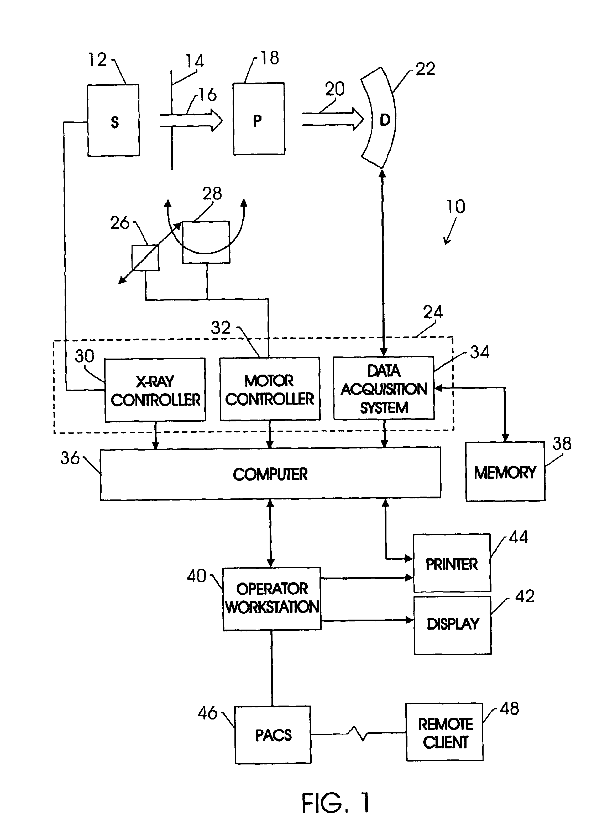
[0021]FIG. 1 illustrates diagrammatically an imaging system 10 for acquiring and processing image data. In the illustrated embodiment, system 10 is a computed tomography (CT) system designed both to acquire original image data, and to process the image data for display and analysis in accordance with the present technique. In the embodiment illustrated in FIG. 1, imaging system 10 includes a source of X-ray radiation 12 positioned adjacent to a collimator 14. In this exemplary embodiment, the source of X-ray radiation source 12 is typically an X-ray tube.

[0022]Collimator 14 permits a stream of radiation 16 to pass into a region in which a subject, such as a human patient 18 is positioned. A portion of the radiation 20 passes through or around the subject and impacts a detector array, represented generally at reference numeral 22. Detector elements of the array produce electrical signals that represent the intensity of the incident X-ray beam. These signals are acquired and processed...


PUM


Abstract

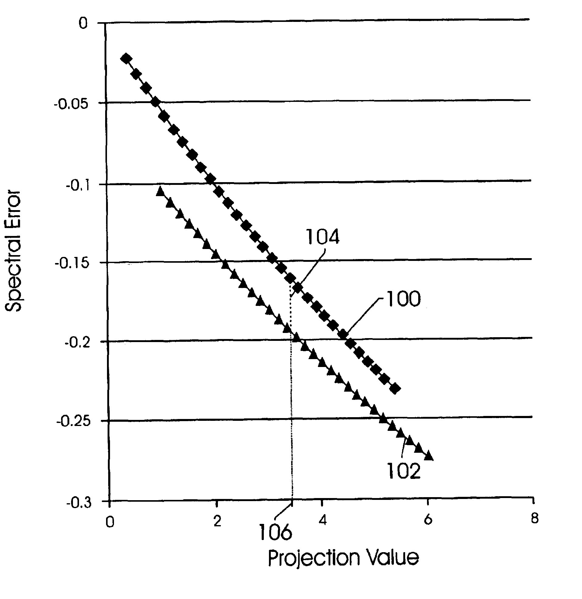
The present technique provides for the estimation and correction of bone induced spectral (BIS) artifacts. Spectral matching is employed to approximate the incident X-ray spectrum attenuated by bone and water with an X-ray spectrum attenuated by water alone. A table can be built to express the amount in apparent projection value shift for objects containing bone and water compared with water-like object when their corresponding normalized spectra match. The BIS error may thereby be determined from existing spectral error data obtained from spectral calibration. A corresponding correction factor may be determined from the shift value.

Description

BACKGROUND OF THE INVENTION[0001]The present invention relates generally to the field of medical imaging. In particular, the following techniques relate to computed tomography imaging systems and the calibration of detectors used in such systems.[0002]Computed tomography (CT) imaging systems measure the intensity of X-ray beams passed through a patient from numerous angles. With sufficient angular coverage around the patient, cross-sectional images can be formed, revealing the inner structure of the scanned object. The images are typically displayed on a cathode ray tube, and may be printed or reproduced on film. A virtual 3-D image may also be produced by a CT examination.[0003]CT scanners operate by projecting fan shaped or cone shaped X-ray beams from an X-ray source that is collimated and passes through the object, such as a patient. The attenuated beams are then detected by a set of detector elements. The detector element produces a signal based on the intensity of the X-ray be...

Claims


Application Information

Patent Timeline
Patent Type & Authority Patents(United States)
IPC IPC(8): A61B6/03A61B6/00
CPCA61B6/032A61B6/585A61B6/583A61B6/501
Inventor WU, XIAOYELEBLANC, JAMES
Owner GENERAL ELECTRIC CO
Learn More