Beam bending apparatus and method of manufacture

a beam bending and beam technology, applied in the field of optical devices, can solve the problems of index gradients produced by ion exchange processes that are time-consuming and expensive, refraction at these surfaces, and each approach has its own limitations, so as to facilitate mass manufacturing, facilitate mass manufacturing, and uniform refractive index

a beam bending and beam technology, applied in the field of optical devices, can solve the problems of index gradients produced by ion exchange processes that are time-consuming and expensive, refraction at these surfaces, and each approach has its own limitations, so as to facilitate mass manufacturing, facilitate mass manufacturing, and uniform refractive index

US6904197B2Inactive Publication Date: 2005-06-07CORNING INC

Image

  • Beam bending apparatus and method of manufacture
  • Beam bending apparatus and method of manufacture
  • Beam bending apparatus and method of manufacture

Examples


example

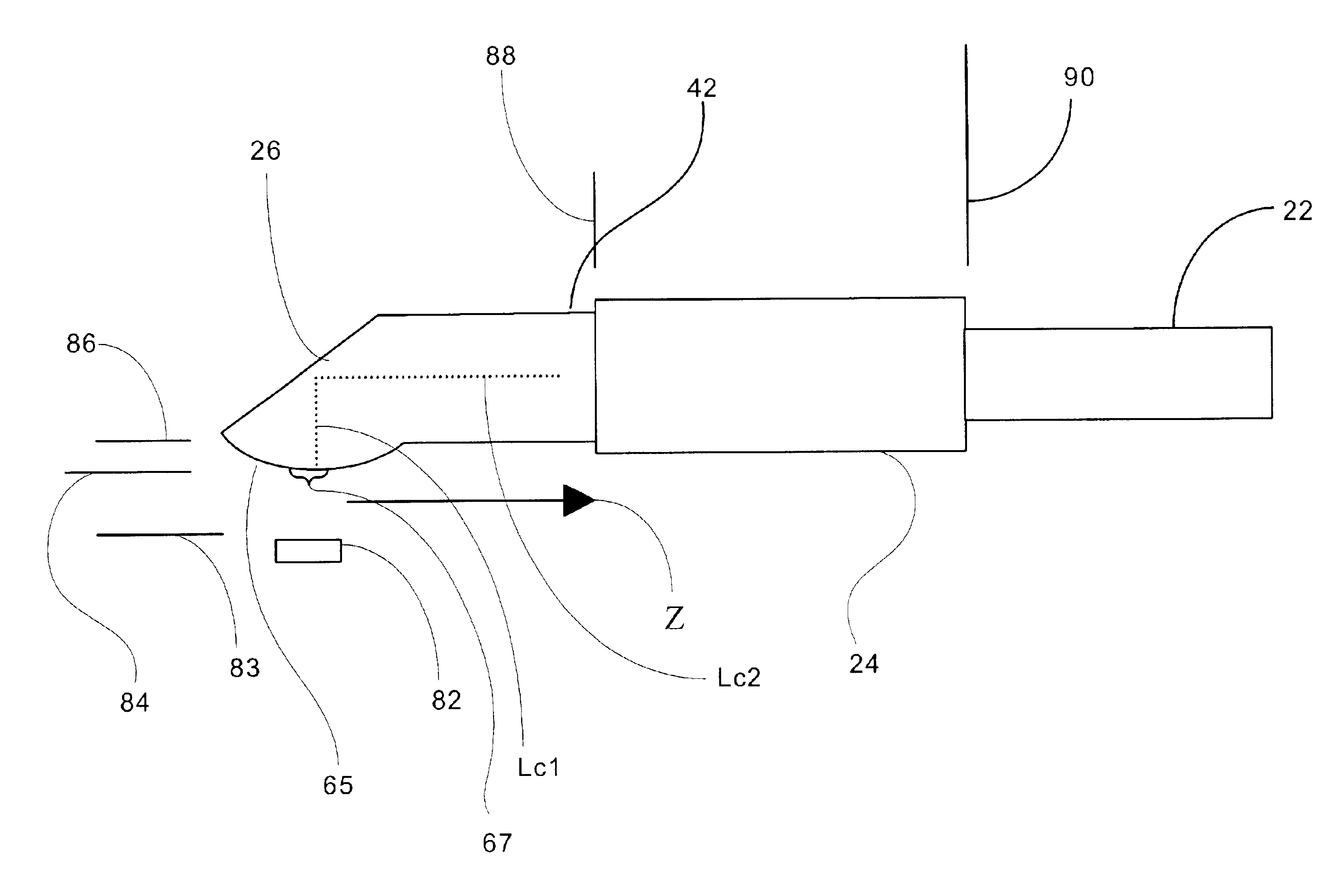
[0080]An example of an off-line or non-in-line beam bending apparatus and optical assembly in accordance with the above-mentioned embodiments of the present invention will now be described.

[0081]An exemplary off-line beam bending apparatus 80, including a ball lens 65 having a biconic curved surface 67 and a beveled reflective surface 26, is shown schematically in FIG. 8 with reference to the variables described below. The exemplary multi-lens apparatus includes a source 82 of an optical signal, in this case a laser diode capable of emitting a signal at an operating wavelength ‘wav’; Mode-field-diameter (MFD) in the x-direction (vertical direction) of wx0 (μm), and MFD in the y-direction of wy0 (μm). The beam from the source 82 propagates through a medium (most commonly air) of index (n1) for a distance (z) before falling on a curved surface 67 with radii of curvature of (RLx) (μm) in the x-direction and (Rly) (μm) in the y-direction that is formed on a spacer rod 42 having a radial...


PUM


Abstract

An apparatus for altering the mode field of an optical signal is disclosed. The apparatus includes a GRIN-fiber lens and a reflective surface disposed at one end of the GRIN-fiber lens, the reflective surface configured to cooperate with the GRIN-fiber lens to redirect the path of the optical signal directed against the reflective surface. A method of manufacturing an apparatus for altering the mode field of an optical signal and an optical assembly are also disclosed.

Description

CROSS REFERENCE TO RELATED APPLICATIONS[0001]This application claims the benefit of U.S. Provisional Application Ser. No. 60 / 361,787, filed Mar. 4, 2002, and entitled, “Beam Altering Fiber Lens Device and Method of Manufacture,” which is hereby incorporated herein by reference.BACKGROUND OF INVENTION[0002]1. Field of the Invention[0003]The present invention relates generally to an optical device for non-in-line mode field interconnections, and more particularly, to a mode-transforming apparatus configured to facilitate high efficiency coupling of optical signals passed between such an apparatus and an optical component and / or other waveguide having a different mode field.[0004]While the present invention is subject to a wide range of applications, it is particularly well suited for coupling sources of elliptically-shaped optical signals, such as laser diodes and semiconductor waveguides, to optical fibers having circularly symmetric mode fields.[0005]2. Technical Background[0006]Cou...

Claims


Application Information

Patent Timeline
07 Jun 2005
Publication
US6904197B2
IPC
G02B6/32; G02B6/26; G02B6/255; G02B6/42; G02B6/30; G02B6/02; H01S5/022
CPC
G02B6/2552; G02B6/262; G02B6/30; G02B6/4214; G02B6/4202; G02B6/4203; G02B6/4206; G02B6/32
Inventors
BHAGAVATULA, VENKATA A.; SHASHIDHAR, NAGARAJA