Seismic analysis using post-imaging seismic anisotropy corrections

an anisotropy correction and seismic data technology, applied in the field of seismic exploration, can solve the problems of loss of certain information that cannot be recovered from stacked data, wave equation migration techniques are typically more robust than kirchoff migration techniques, and traditional seismic processing, which is based on, and achieves more accurate results

Inactive Publication Date: 2005-06-07
LANDMARK GRAPHICS CORP
View PDF9 Cites 55 Cited by
  • Summary
  • Abstract
  • Description
  • Claims
  • Application Information

AI Technical Summary

Benefits of technology

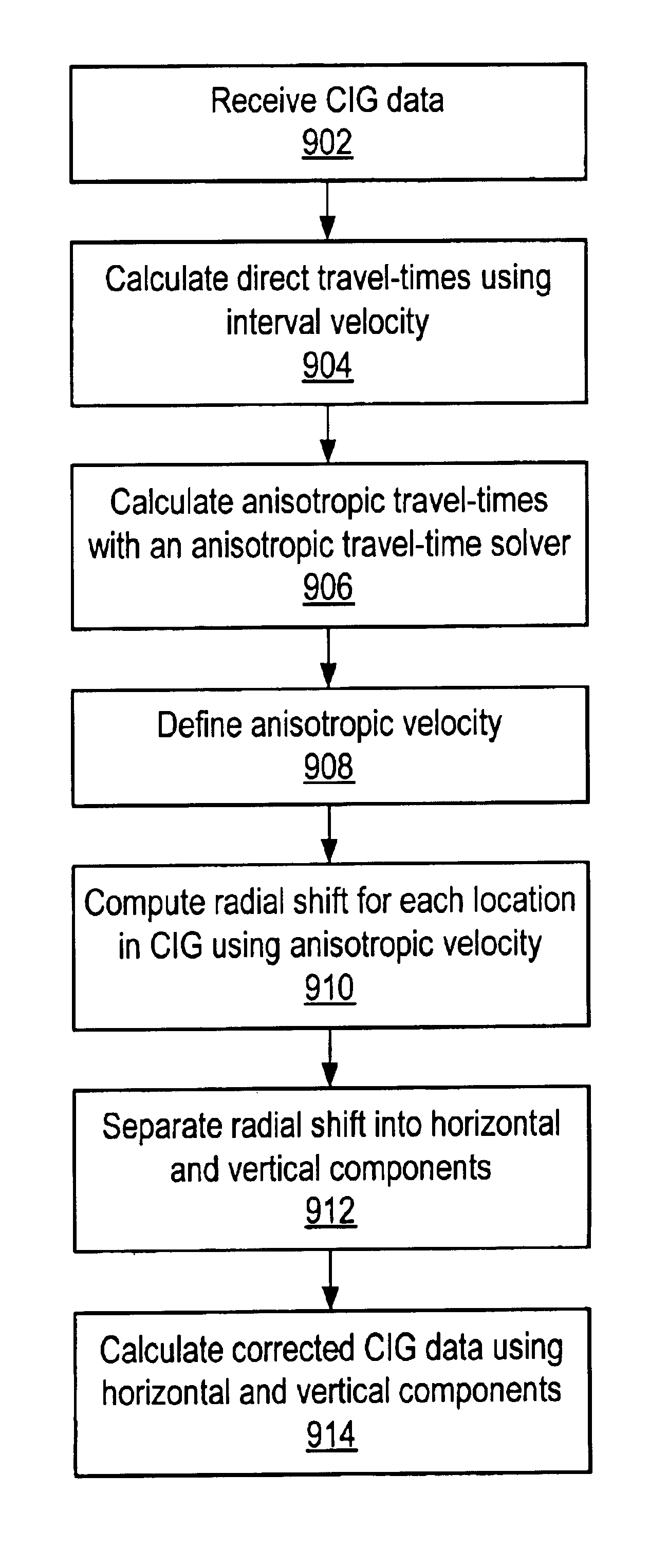
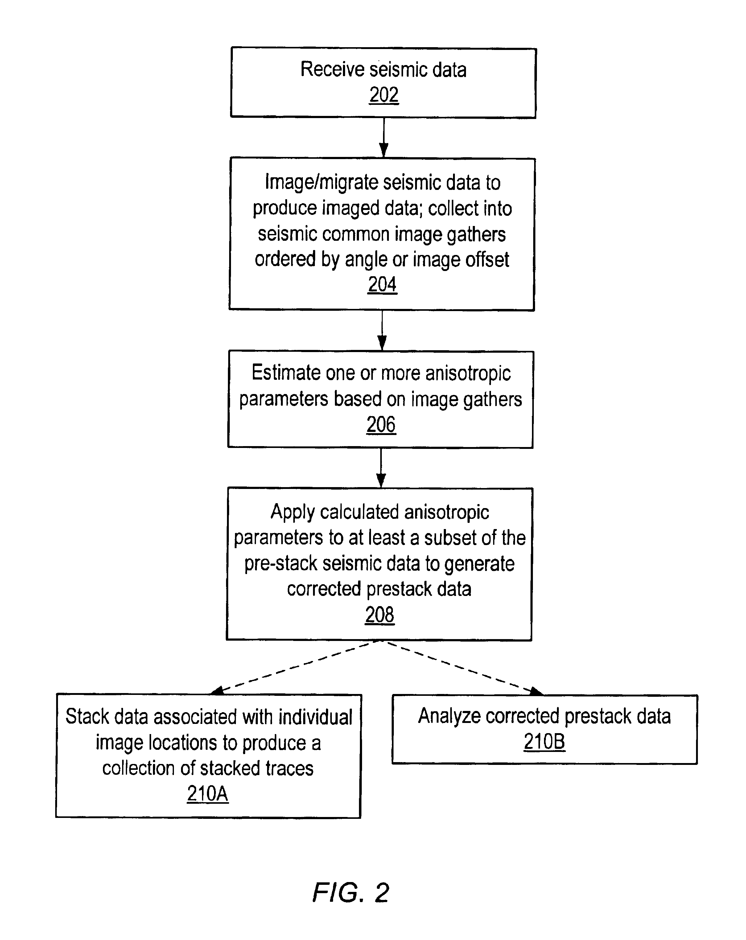
[0036]In one embodiment, once the anisotropic parameters are determined, the pre-stack imaging process may be repeated using a seismic processing algorithm modified to account for at least vertical transverse isotropic (VTI) assumptions. Alternatively, the relative vertical, horizontal, radial, spatial or other combination of shifts and / or amplitude, phase or other anisotropic corrections may be applied to any or every image gather, providing an alternative to a full re-imaging operation. After the image gathers are corrected, common image gather stacks may produce images with seismic energy positioned more accurately than data with no anisotropic corrections. It is noted that amplitude vs. angle (AVA), amplitude vs. offset (AVO), pre-stack inversion, and many other pre-stack analysis techniques may produce more accurate results using these corrected gathers.

Problems solved by technology

The stacking process also results in the loss of certain information that cannot be recovered from the stacked data, so the stacking process is used selectively in accordance with issues such as, but not limited to, the interpretation objectives of the seismic survey.
Wave equation migration techniques are typically more robust than Kirchoff migration techniques, but are also typically more computationally intensive.
As a consequence, traditional seismic processing, which is based upon an isotropic subsurface assumption, will not properly “correct” for properties like seismic travel times during operations like normal moveout and pre-stack imaging.
Anisotropic parameters, such as the Thomsen parameters, are difficult to estimate, as they require relative measurements of seismic waves reflecting from both “flat” and “dipping” rock formations for approximately the same traveltime (Alkhalifah 1997).
As pre-stack migration can take days or even weeks to perform, techniques that employ multiple migrations or otherwise require additional application of pre-stack migration can be very costly.

Method used


Image

  • Seismic analysis using post-imaging seismic anisotropy corrections
  • Seismic analysis using post-imaging seismic anisotropy corrections
  • Seismic analysis using post-imaging seismic anisotropy corrections

Examples


Embodiment Construction

[0054]Reshef (1996) described a unique output domain for seismic imaging, applicable to 2D or 3D data and time or depth imaging. In these gathers, referred to herein as “image offset gathers”, being a special form of image gather, where the “traditional” source-to-receiver offset distance for the horizontal axis is replaced with a value of source-to-common-surface-location (CSL) distance plus common-surface-location-to-receiver distance. Common surface location (CSL) is the surface spatial location corresponding to the subsurface image or reflection point (CIP / CRP) of an image gather. Reshef noted specific advantageous characteristics of these gathers, such as separating energy reflected from “flat” and from “dipping” rock formations. Specifically, energy from “flat” subsurface reflectors tends to collect on the “near” traces (smaller shot-image-receiver distance), while energy from more and more steeply dipping subsurface reflectors, i.e., “dipping energy”, tends to collect on furt...


PUM


Abstract

System and method for performing anisotropy corrections of post-imaging seismic data for a subsurface formation. The method may receive seismic data, preferably pre-stack seismic data comprising a plurality of traces, e.g., collected from a plurality of source and receiver locations. The seismic data may be imaged / migrated to produce imaged seismic data, which is organized into an arrangement that preserves aspects of the relative seismic propagation angle in the subsurface. One or more anisotropic parameters and corresponding corrections may be determined by analyzing the organized imaged seismic data. The determined parameters or corrections may be used to correct at least a subset of the imaged seismic data, thereby producing corrected seismic data which is useable in analyzing the formation. The corrected data may then optionally be stacked to produce a collection of corrected stacked traces, and / or analyzed as desired. The pre-stack data and / or the corrected seismic data may optionally be displayed.

Description

PRIORITY CLAIM[0001]This application claims benefit of priority of U.S. provisional application Ser. No. 60 / 427,312 titled “SEISMIC ANALYSIS USING POST-IMAGING SEISMIC ANISOTROPY CORRECTIONS” filed Nov. 12, 2002, whose inventors are Moshe Reshef and Murray W. Roth which is hereby incorporated by reference in its entirety.FIELD OF THE INVENTION[0002]The present invention generally relates to seismic exploration, and more particularly, to a system and method for performing anisotropy corrections of post-imaging seismic data.DESCRIPTION OF THE RELATED ART[0003]Seismic exploration involves the study of underground formations and structures. In seismic exploration, one or more sources of seismic energy emit waves into a region of interest, such as a formation. These waves enter the formation and may be scattered, e.g., by reflection or refraction. One or more receivers sample or measure the reflected waves, and the resultant data recorded. The recorded samples may be referred to as seism...

Claims


Application Information

Patent Timeline
Patent Type & Authority Patents(United States)
IPC IPC(8): G01V1/36G01V1/28G01V1/30
CPCG01V1/362G01V1/303
Inventor RESHEF, MOSHEROTH, MURRAY W.
Owner LANDMARK GRAPHICS CORP
Why Eureka
Try Eureka