
Apparatus for making seamless siding panel

Inactive Publication Date: 2005-06-14
US SEAMLESS
View PDF34 Cites 19 Cited by
  • Summary
  • Abstract
  • Description
  • Claims
  • Application Information

AI Technical Summary

Benefits of technology

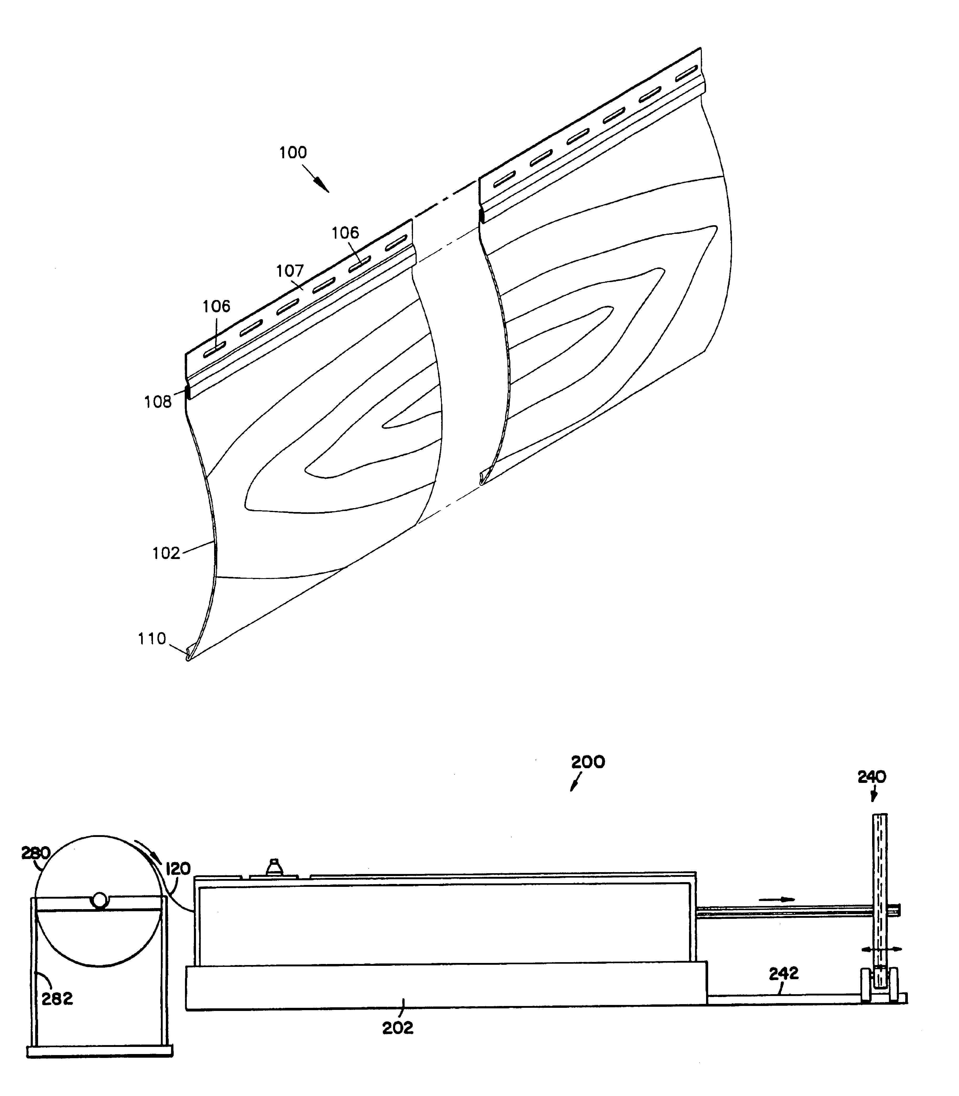
[0011]Each siding panel includes an arcing portion having an outer surface with a diameter substantially that corresponding to a log type home construction. In addition, the panel may be painted or otherwise have a color pattern to simulate wood grain and may be embossed with a wood grain texture. The panels preferably have a hook type portion on the lower edge of the panel and a flange for mounting and for engaging the hook type portion along an upper edge of the panel. The flange preferably includes mounting holes or other structure for mounting to the wall of a building. The panel preferably includes Styrofoam or other insulation beneath the arc portion, providing support to the arcing portion of the metal panels as well as improved durability and protection. The panels are seamless and cut to the desired length from a continuous coil of blank material at the job site.
[0013]The blank material is first fed through a punch station wherein a roller includes a plurality of punches extending outward from the periphery of the roller at one end to form spaced apart holes along one edge of the blank material for mounting purposes. Following punching on the mounting holes, the material is fed through an embossing station wherein a pair of rollers engage the material and press a contoured surface onto the blank coil of metal. It has been found that embossing not only provides improved texture for hiding imperfections and for improved aesthetics resembling wood grain, but also provides unexpected improved support as compared to arced panels that are not embossed.
[0015]The panels are cut to length at a cutting station at the exit end of the rollers. The cutting station is preferably mounted on a sliding or other movable frame so that the desired length required for each siding panel can be easily achieved for optimum fit. The cutting station includes a die having an arcing upper edge generally conforming to the inner periphery of the arcing section of the siding panels. A pivoting blade includes a concave edge substantially complementary to the panels to provide a cleaner cut at the end of the panel sections.

Problems solved by technology

Although textured sidings, such as vinyl siding are well known, it is more difficult to form a textured harder siding element, such as metal siding from a blank coil of material.
Providing texture to the siding encounters special problems when the siding is a metal siding as the material is generally quite hard and more difficult to emboss or texture than other siding materials.
Providing an arc to the element for a seamless siding system is especially difficult as the material must be formed by a portable device at the job site.
Providing flanges and texture and an arc all with a portable device is a special challenge for seamless metal siding.

Method used


Image

  • Apparatus for making seamless siding panel
  • Apparatus for making seamless siding panel
  • Apparatus for making seamless siding panel

Examples


Embodiment Construction

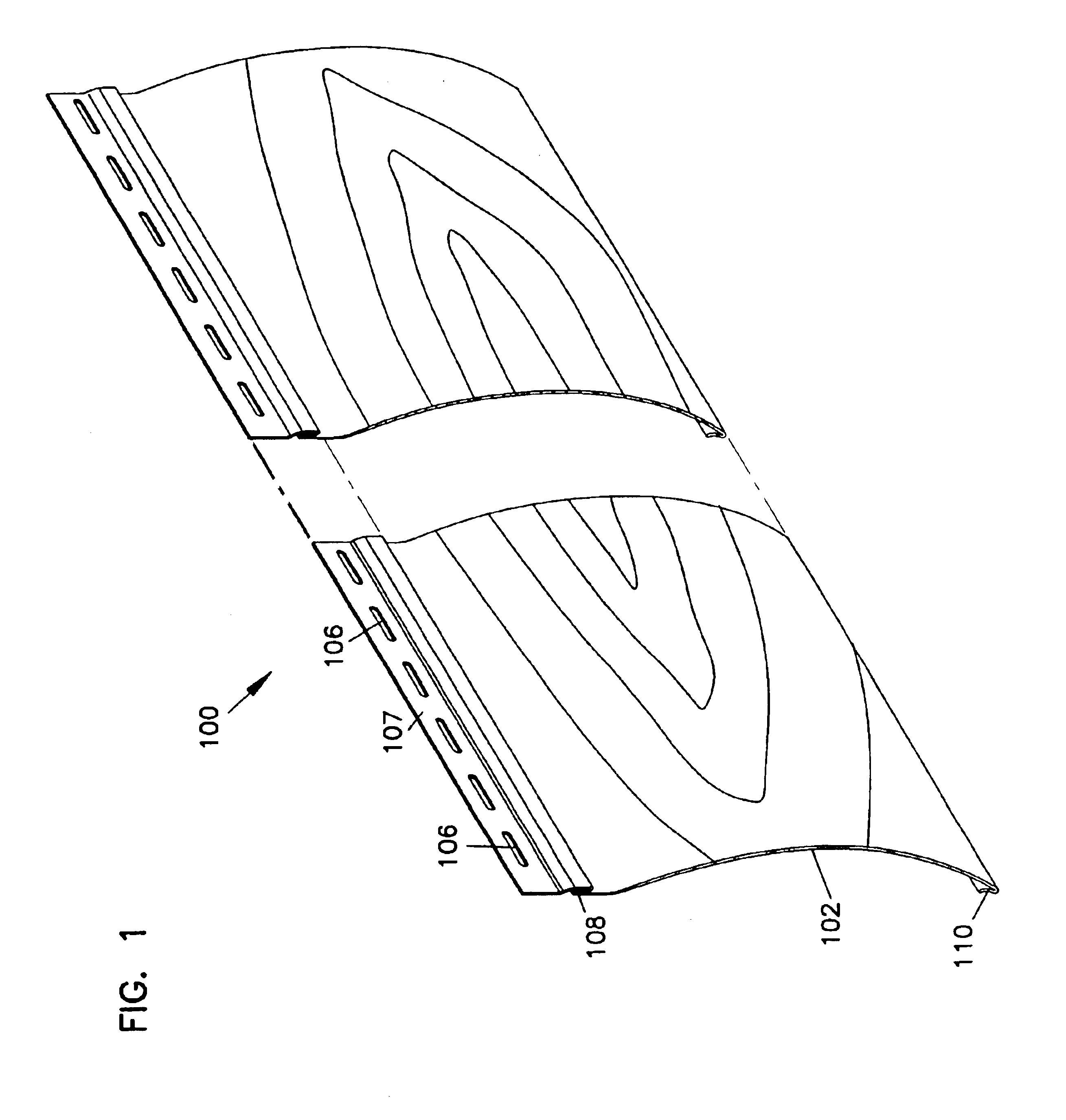
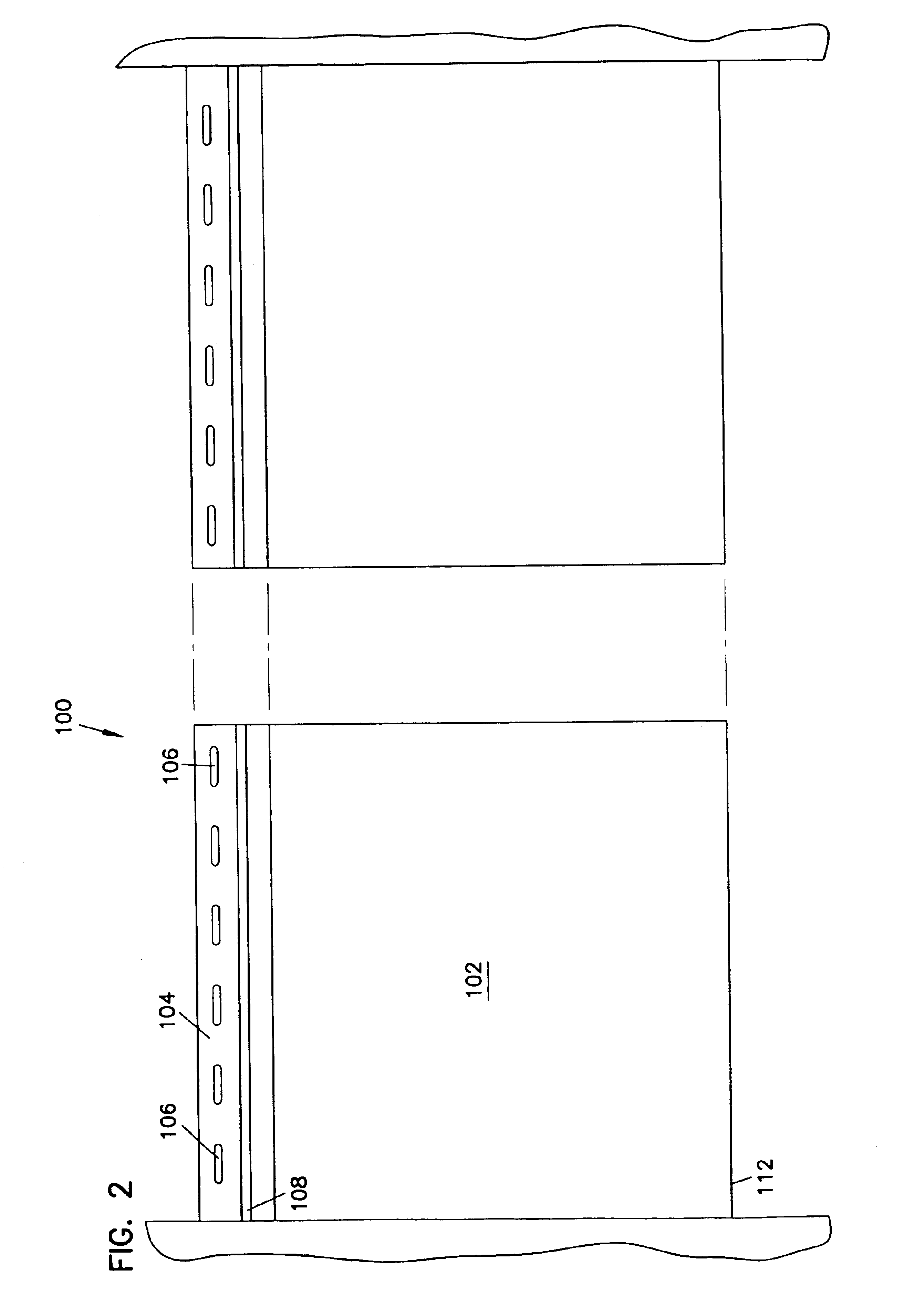
[0038]Referring now to the drawings, wherein like reference numerals and letters indicate corresponding structure throughout the several views, in particular referring to FIG. 1, there is shown a seamless siding panel, generally designated 100. The panel 100 includes an arcing outer surface 102 and a flange 104 along a first edge, as also shown in FIGS. 2 and 3. The upper flange 104 has a hook portion 108 formed therein that engages a complementary bottom hook 110 to join the panels 100 together to form extended siding covering the side of the building, as shown in FIG. 3. The bottom hook portion 110 may also include spaced apart weep holes 112 to allow water to drain from the panel 100. The flange 104 includes spaced apart mounting holes 106 for attaching the panels 100 to the side of a building.

[0039]Foam insulation, molded polystyrene, or other support material 114 substantially follows the interior of the arcing portion 102. Referring again to FIGS. 1 and 2, the exterior of the ...


PUM

PropertyMeasurementUnit
Radiusaaaaaaaaaa
Bending strengthaaaaaaaaaa

Abstract

A siding system includes panels having a facing element with a convex front face portion. A first connecting portion extending along an upper edge and a second connecting portion at a lower edge is adapted to engage the first connecting portion of an adjacent lower siding panel. Mounting holes at a top edge of the facing element provide for mounting the siding panel to a vertical surface. A support element, such as foam insulation attaches to a rear surface of the facing element. A machine for making the metal siding panels has a feeder and multiple roller sets. First ones of the rollers have a concave portion and complementary second ones of the rollers have a convex portion. The concave portion first roller set has a larger radius profile than the last roller set to roll form the siding from a coil of blank material. Bending rollers form the mounting structure of the panels. Embossing rollers forming an embossed pattern on the face of the panels.

Description

CROSS REFERENCE TO RELATED APPLICATIONS[0001]This application is a divisional application of application Ser. No. 09 / 747,367 filed Dec. 21, 2000 ABN which application(s) are incorporated herein by reference.BACKGROUND OF THE INVENTION[0002]1. Field of the Invention[0003]The present invention relates to a siding element having an appearance of log construction, and in particular to a metal seamless siding element, an apparatus for making the siding and a method of making the siding.[0004]2. Description of the Prior Art[0005]Various types of siding for houses and other structures have been developed. Vinyl siding, aluminum siding and steel siding have all been developed as low maintenance or maintenance free siding options that do not require painting and other normal maintenance tasks. Some types of siding provide the additional advantage of being seamless, wherein siding elements are cut to a desired length spanning the entire distance from a corner or interruption in the siding to ...

Claims


Application Information

Patent Timeline
IPC IPC(8): B21H8/00E04F13/08B21B27/00B21B1/22B21H7/00
CPCE04F13/0864B21H8/00B21B1/227B21B27/005B21H8/005
Inventor BULLINGER, MICHAEL J.COOPER, RUSSELL L.
Owner US SEAMLESS
Learn More