
Reciprocating piston device

a piston motor and reciprocating technology, applied in the direction of machines/engines, belts/chains/gearings, machine/engines, etc., can solve the problems of increasing the cost of crankshafts, so as to reduce the volume and weight, the effect of reducing the cost and increasing the usefulness

Inactive Publication Date: 2005-06-14
HEIFETS NUHIM
View PDF7 Cites 32 Cited by
  • Summary
  • Abstract
  • Description
  • Claims
  • Application Information

AI Technical Summary

Benefits of technology

"The present invention is a reciprocating piston motor that has a decreased size and weight for a given power output. This results in a lower cost and greater usefulness due to its ability to fit into smaller engine compartments. The motor uses shorter pistons and less complicated crankshafts, while having a desirable self-balancing character that minimizes internal loads. The engine has a unique design with pairs of pistons that are kinematically connected to a single intermediate shaft, which oscillates rotationally in response to back and forth movement of the pistons. The crankshaft design is greatly simplified with only a single crank pin, irrespective of the number of pistons in the engine. This results in a relatively short and light weight crankshaft, with a reduction in overall cost of the engine. The engine has a reduced size for a given power output and is relatively low cost."

Problems solved by technology

The conventional crankshaft is relatively long and heavy, especially in the case of eight cylinder in-line engines.
The crankshaft cost becomes a major factor.
Also, the crankshaft bearings have to be relatively heavy and numerous to absorb momentary unbalanced forces.
Another problem with conventional piston engines is that each piston lacks lateral support.
The long piston requirement and crankshaft design requirements tend to unduly increase the overall size and weight of the engine, especially with engines having a large number of cylinders.
However, such designs have their own problems, associated with the require-ment for an increased number of shafts, and gears.
The drive system described in U.S. Pat. No. 5,673,665 is relatively complex.
The drive system is quite complex.

Method used


Image

  • Reciprocating piston device
  • Reciprocating piston device
  • Reciprocating piston device

Examples


Embodiment Construction

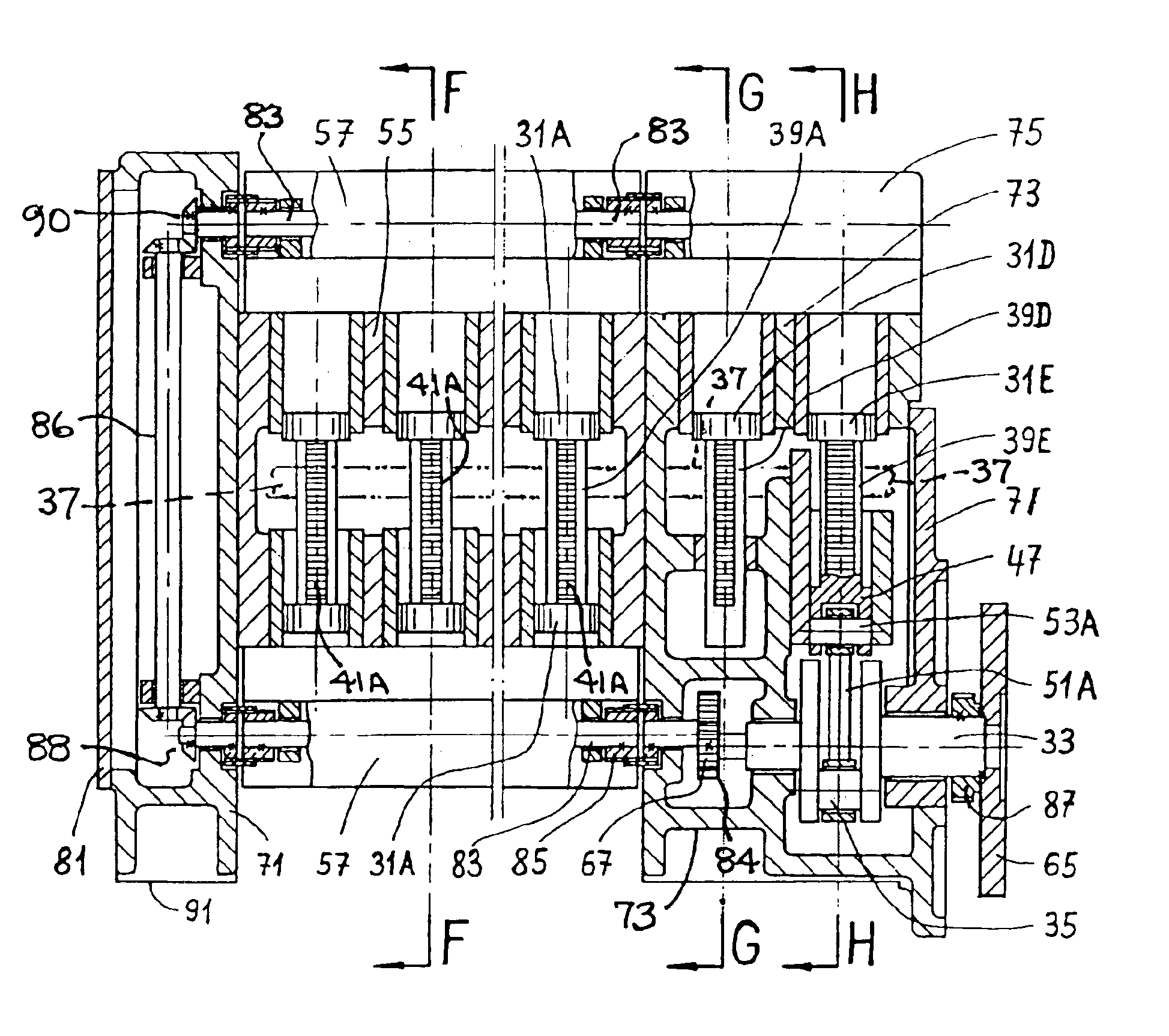
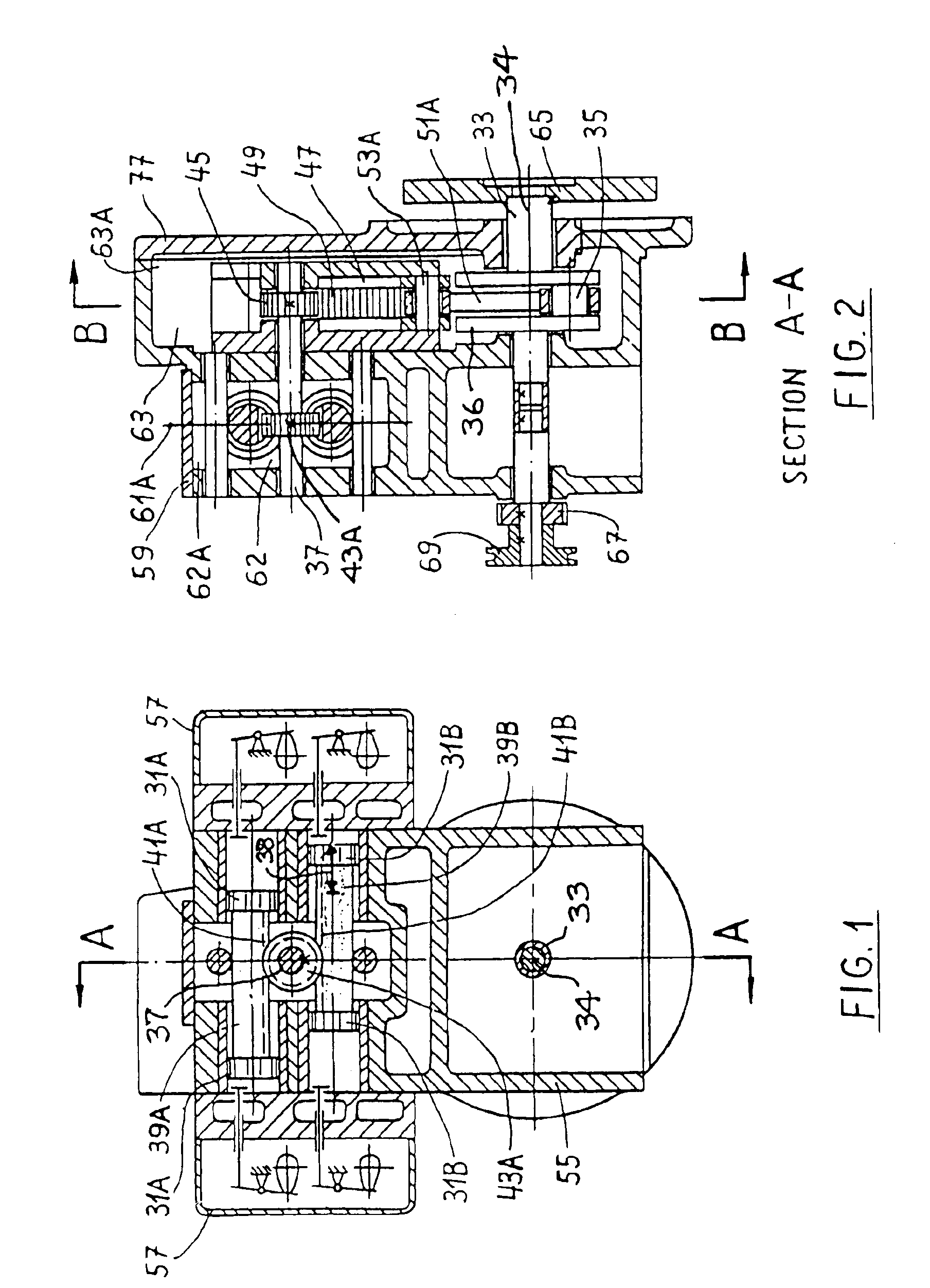
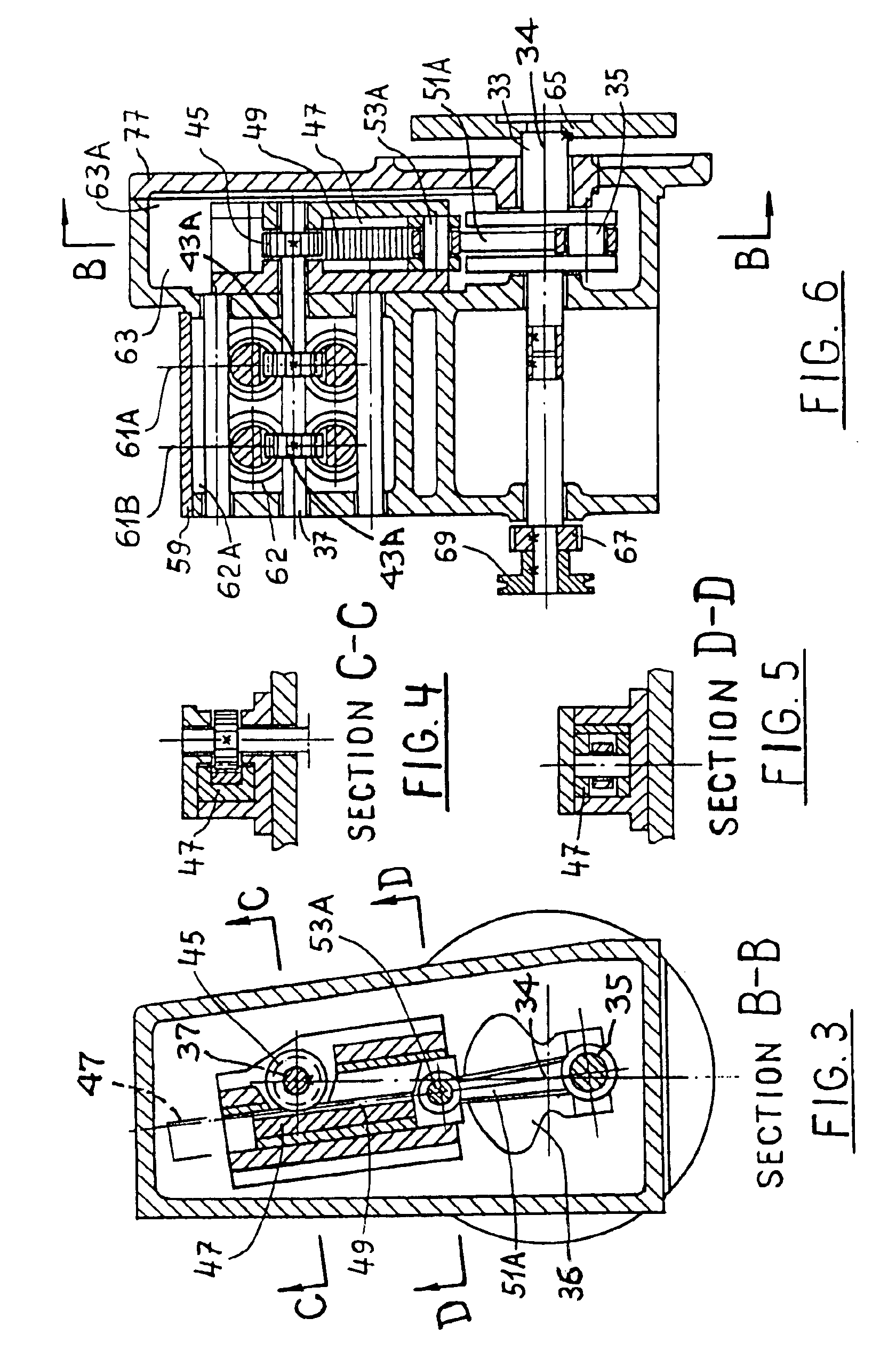
[0038]Referring to FIGS. 1 through 5, there is shown a four stroke cycle engine having four pistons, and constructed according to the present invention. The engine (or motor) includes a case 55 that supports two cylinder heads 57 containing the usual intake and exhaust valves, together with the associated cam shafts and timing gear employed in four stroke cycle engines.

[0039]This particular engine has four cylinders and associated pistons 31A and 31B that are grouped in two in-line pairs. The two aligned pistons 31A are rigidly connected together by a bar (or rod) 39A and the two aligned pistons 31B are rigidly connected together by a bar (or rod) 39B. Each bar 39A or 39B has teeth 41A or 41B extending therealong, whereby the respective bar constitutes a toothed rack.

[0040]A single pinion gear 43A is in simultaneous mesh with both toothed racks 41A and 41B, so that each rack can serve as a driver for the pinion gear at different times in the engine cycle. Pinion gear 43A is carried ...


PUM


Abstract

A reciprocating piston engine (or motor) includes plural reciprocating pistons operatively connected to a single intermediate oscillating shaft, and a crankshaft having a single crank pin operatively connected to the oscillating shaft, so that the crankshaft experiences one complete revolution for each back-and-forth reciprocation of the pistons. The connection between the pistons and the oscillating shaft can include a rack-pinion drive system or a link-lever drive system. The connection between the oscillating shaft and the crankshaft can include a sector gear in mesh with a toothed rack that operates a connecting rod attached to the crank pin; alternately a lever-connecting rod drive mechanism can be used between the oscillating shaft and the crankshaft.

Description

[0001]Disclosure documents 507456 and 523965 respectively preceded Applicant's patent application as follows:FIELD OF THE INVENTION[0002]This invention relates to reciprocating piston motors, e.g., internal combustion engines, steam engines and fluid motors (air or hydraulic). A principal use of the invention is in internal combustion engines.BACKGROUND OF THE INVENTION[0003]In many conventional four cycle engines each piston is individually connected to the drive shaft by means of a connecting rod and crank arm. The drive shaft comprises a crankshaft having one crank pin and counterweight for each piston.[0004]The conventional crankshaft is relatively long and heavy, especially in the case of eight cylinder in-line engines. In order to balance the internal engine forces, several relatively heavy counterweights are required (one for each piston). The crankshaft cost becomes a major factor. Also, the crankshaft bearings have to be relatively heavy and numerous to absorb momentary unb...

Claims


Application Information

Patent Timeline
Patent Type & Authority Patents(United States)
IPC IPC(8): F02B75/32F02B75/24F02B75/28
CPCF02B75/24F02B75/32F02B75/28Y10T74/18176
Inventor HEIFETS, NUHIM
Owner HEIFETS NUHIM
Learn More