Subsea mud pump and control system

a control system and subsea mud technology, applied in the direction of piston pumps, positive displacement liquid engines, borehole/well accessories, etc., can solve the problems of difficult to accurately model both non-linear responses, uneconomical wells to drill and produce, and difficult to precisely adjust the control system

Inactive Publication Date: 2005-06-14
HYDRIL USA MANUFACTURING LLC
View PDF8 Cites 99 Cited by
  • Summary
  • Abstract
  • Description
  • Claims
  • Application Information

AI Technical Summary

Benefits of technology

[0018]In one aspect, the invention relates to sub-sea mud pump system includes a plurality of pump units, and each pumping unit includes a plurality of pumping elements. Each pumping element includes a pressure vessel with a first and a second chamber, a separating member between the first and second chambers, a measurement device adapted to measure the volume of at least one of the first and second chambers, a hydraulic inlet control valve and a hydraulic outlet control valve coupled to the first chamber, a mud suction valve and a mud discharge valve coupled to the second chamber. The first chamber is hydraulically coupled to receive and discharge a hydraulic fluid, and the second chamber is hydraulically coupled to receive and discharge a drilling fluid. The separating member is adapted to move within its the pressure vessel in response to a pressure differential between the first and second chambers. The pump system also includes a hydraulic control unit adapted to control the plurality of pump units.

Problems solved by technology

In deep water drilling operations, the total cost of installing a large number of casing strings, combined with smaller oil and gas production rates possible through reduced diameter casing, can often result in wells which are uneconomical to drill and produce.
The control system is difficult to precisely adjust because it has proven difficult to accurately model both the non-linear responses of many of the hydraulic components of the system and the wellbore hydraulic characteristics over time.
In practice, significant load changes from a stable pump operating condition, such as step load changes of plus or minus fifty percent, have been found to cause instability in the system.
Further, the response of the variable displacement hydraulic pump to the control signals, which is adequate at low and steady pumping rates, has proven to be inadequate at higher mud pump rates (e.g., pump rates above about 4-5 strokes per minute).
Moreover, because the hydraulic valves controlling the mud pumping elements in the disclosed arrangement must have a high Cv to allow the mud pumps to operate at high flow rates, the disclosed control valve arrangement may be prone to hydraulic “water hammer” effects whenever the large bore valves open or close under differential pressure during the pumping cycle, especially at high pump rates.

Method used


Image

  • Subsea mud pump and control system
  • Subsea mud pump and control system
  • Subsea mud pump and control system

Examples


Embodiment Construction

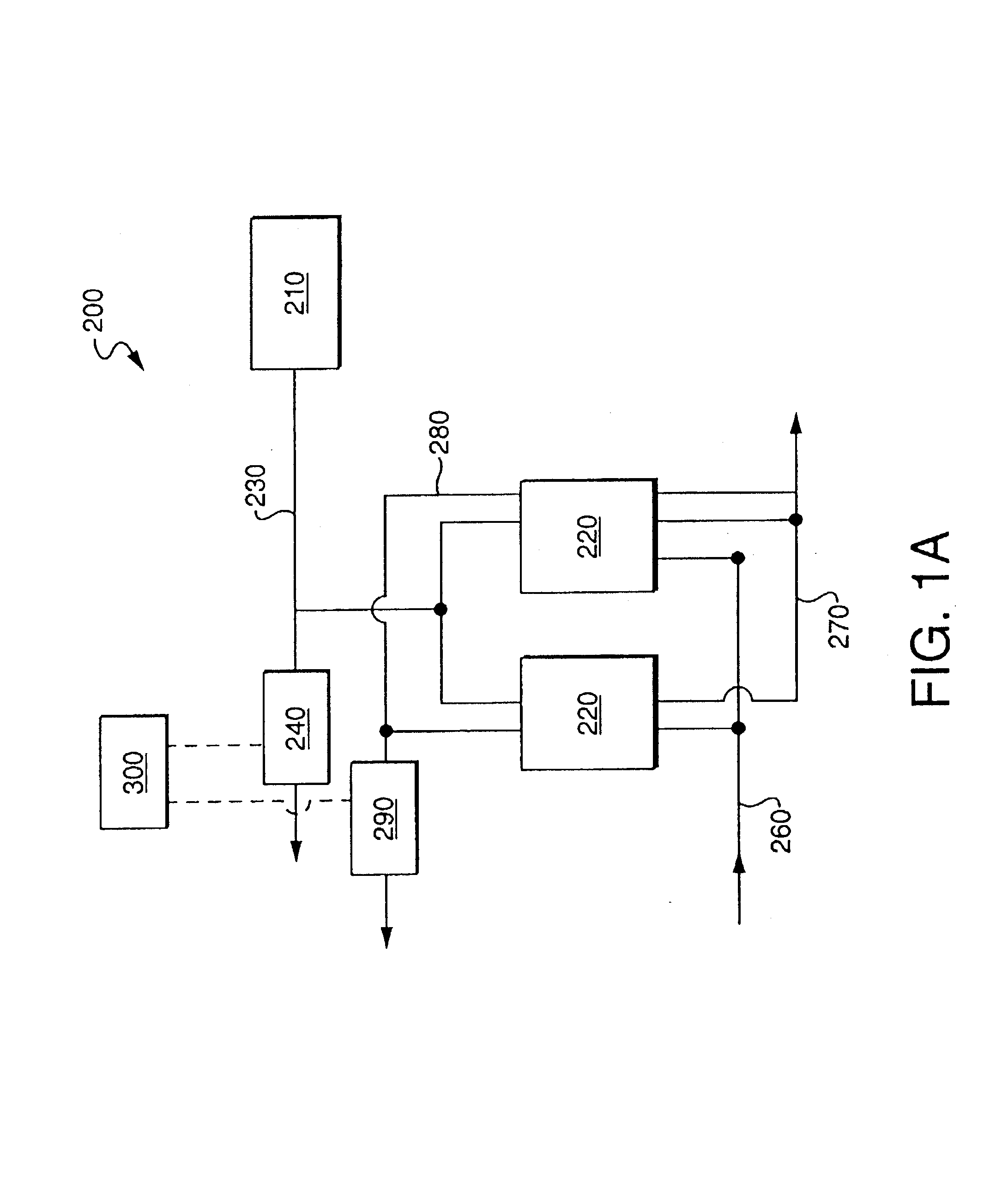
[0031]FIG. 1A shows a simplified schematic view of an embodiment of the invention. A subsea pump 200 comprises a hydraulic power supply 210 and pumping elements 220. The hydraulic power supply 210 is hydraulically coupled to the pumping elements 220 by a hydraulic fluid supply line 230. The hydraulic fluid supply line 230 is also coupled to a valve 240. The valve 240 is operatively coupled to a valve controller 300 that is adapted to control a rate and time of application of hydraulic fluid to the pumping elements 220. A flow of drilling fluid is supplied to the pumping elements through an inlet line 260.

[0032]The flow of hydraulic fluid energizes the pumping elements 220, and the flow of hydraulic fluid into the pumping elements 220 generates a flow of drilling fluid out of the pumping elements 220 through a discharge line 270. Similarly, a flow of drilling fluid into the pumping elements 220 generates a flow of hydraulic fluid out of the pumping elements 220. Hydraulic fluid flows...


PUM


Abstract

A sub-sea mud pump system includes a plurality of pump units, and each pumping unit includes a plurality of pumping elements. Each pumping element includes a pressure vessel with a first and a second chamber, a separating member between the first and second chambers, a measurement device adapted to measure the volume of at least one of the first and second chambers, a hydraulic inlet control valve and a hydraulic outlet control valve coupled to the first chamber, a mud suction valve and a mud discharge valve coupled to the second chamber. The first chamber is hydraulically coupled to receive and discharge a hydraulic fluid, and the second chamber is hydraulically coupled to receive and discharge a drilling fluid. The separating member is adapted to move within its the pressure vessel in response to a pressure differential between the first and second chambers. The pump system also includes a hydraulic control unit adapted to control the plurality of pump units.

Description

CROSS REFERENCE TO RELATED APPLICATIONS[0001]This is a continuation in part of U.S. patent application Ser. No. 09 / 923,287 filed on Aug. 6, 2001 and assigned to the assignee of the present invention, and issued as U.S. Pat. No. 6,505,691. Application Ser. No. 09 / 923,287 is a continuation-in-part of U.S. patent application Ser. No. 09 / 276,404 filed on Mar. 25, 1999 and assigned to the assignee of the present invention; which claims the benefit of U.S. Provisional Patent Application Ser. No. 60 / 079,641, filed on Mar. 27, 1998.BACKGROUND OF INVENTION[0002]1. Field of the Invention[0003]The invention relates generally to offshore drilling systems which are used to drilling subsea wells. More particularly, the invention relates to a subsea pump and an associated control system for use in offshore drilling systems.[0004]2. Background Art[0005]In conventional offshore drilling operations from, for example, a floating drilling vessel, a large diameter marine riser (e.g., a 21 inch marine ri...

Claims


Application Information

Patent Timeline
Patent Type & Authority Patents(United States)
IPC IPC(8): E21B33/08E21B21/00E21B33/02E21B21/08E21B21/01E21B43/34E21B43/36F04B43/06F04B19/00
CPCE21B21/001E21B21/01E21B21/08F04B43/06E21B43/36F04B19/003E21B33/085E21B2021/006E21B21/085
Inventor JUDGE, ROBERT A.NGUYEN, DAT MANHWADE, HAROLDBROOKS, RONALD D.
Owner HYDRIL USA MANUFACTURING LLC
Why Eureka
Try Eureka