Metal gasket

a technology of metal gaskets and gaskets, applied in the direction of fluid pressure sealing joints, engine seals, pipes, etc., can solve the problems of leakage at the welded portion, decreased thickness, and difficulty in bending and welding, and achieve the effect of small tightening for

Active Publication Date: 2005-06-14
NICHIAS CORP
View PDF13 Cites 58 Cited by
  • Summary
  • Abstract
  • Description
  • Claims
  • Application Information

AI Technical Summary

Benefits of technology

[0014]Accordingly, a main object of the present invention, which was made to overcome the drawbacks of the conventional metal gaskets, is to provide a gasket that has a s

Problems solved by technology

In the case where it is mounted for use where an ultra-high vacuum is required, leakage may be produced at the welded portion where the thickness is decreased.
Further, when the gasket has a very small diameter of, for example, 10 mm, a problem arises in that it is difficult to bend and weld it as well as there is also a disadvantage that a very strong bolt is required to apply a strong tightening force.
However, it is required to reduce the tightening force of the gasket necessary to seal because the diameter of the bolt small and it is difficult to apply a large force to the bolt.
However, since these metal C-ring gaskets with the projections secure a sealing property

Method used


Image

  • Metal gasket
  • Metal gasket
  • Metal gasket

Examples


embodiment 1

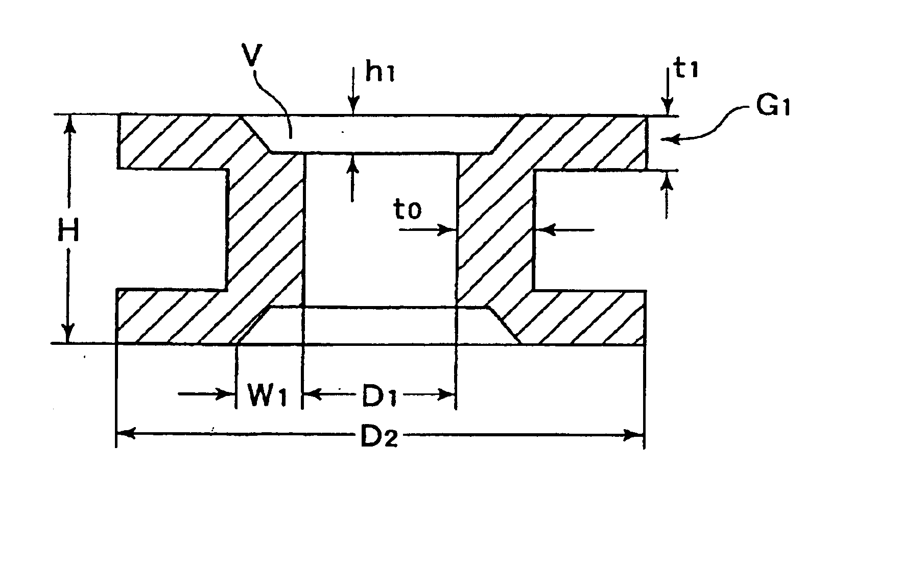
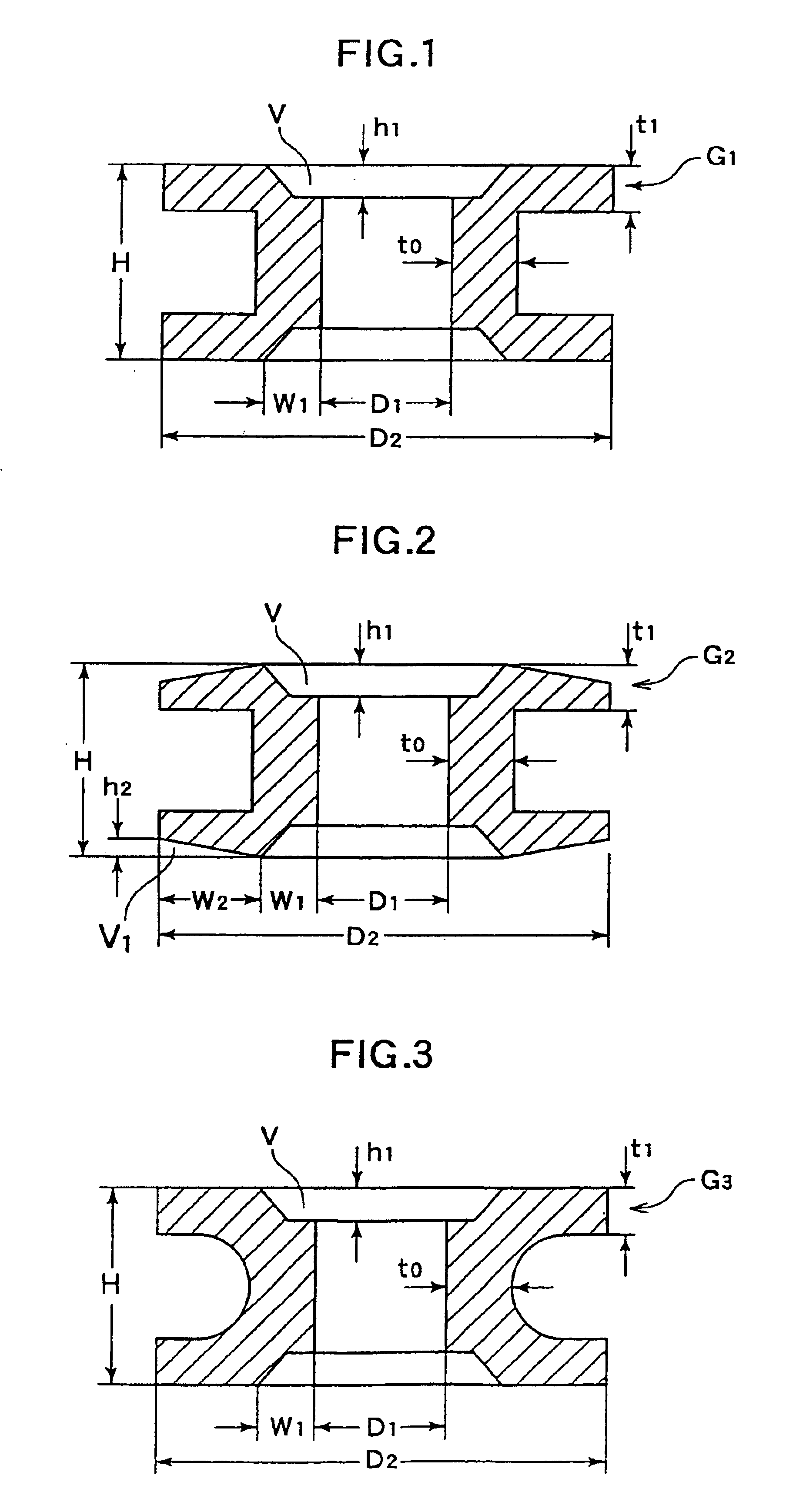
[0041]In an embodiment 1, a round metal bar made of SUS 316L and having an outside diameter of 8.0 mm was cut to a length of 1.7 mm, and a metal gasket G1 as shown in FIG. 1 was obtained by cutting the metal bar. The gasket was formed to have a C-shaped cross section and had an outside diameter D2 of 7.2 mm, an inside diameter D1 of 4.6 mm, a height H of 1.60 mm, a the bight section having a central wall thickness t0 of 0.56 mm, and a wall thickness t1 of 0.33 mm in the portions thereof in contact with opponent surfaces. Further, the gasket had voids V each having a trapezoidal cross section and formed to the innermost circumferential portions of the two sealing surfaces thereof in contact with flanges. Each void V had a width w1 of 0.33 mm, a height h1 of 0.11 mm and an area S of 0.03 mm2. Thereafter, the metal gasket G1 was subjected to annealing and electrolytic polishing, thereby the gasket having surface hardness of 200 Hv was obtained.

embodiment 2

[0042]In an embodiment 2 which was made by the same method as that of the embodiment 1, a round metal bar having an outside diameter of 8.0 mm was cut to a length of 1.7 mm, and a metal gasket G2 as shown in FIG. 2 was obtained by cutting the metal bar. The gasket was formed to have a U-shaped cross section and had an outside diameter D2 of 7.2 mm, an inside diameter D1 of 4.6 mm, a height H of 1.60 mm, the bight section having a central wall thickness t0 of 0.56 mm, and a wall thickness t1 of 0.33 mm in the portions thereof in contact with opponent surfaces. Further, the gasket G2 had voids V each having a trapezoidal cross section and formed to the innermost circumferential portions of the two sealing surfaces thereof in contact with flanges. Each void V had a width w1 of 0.33 mm, a height h1 of 0.11 mm and an area S of 0.03 mm2. Furthermore, the gasket G2 had voids V1 each having a triangular cross section and formed toward the outer circumferences of the two sealing surfaces in ...

embodiment 3

[0043]In an embodiment 3 which was made by the same method as that of the embodiment 1, a round metal bar having an outside diameter of 8.0 mm was cut to a length of 1.7 mm, and a metal gasket G3 as shown in FIG. 3 was obtained by cutting the metal bar. The gasket was formed to have a U-shaped cross section and had an outside diameter D2 of 7.2 mm, an inside diameter D1 of 4.6 mm, a height H of 1.60 mm, the bight section having a central wall thickness to of 0.56 mm, and a wall thickness t1 of 0.33 mm in the portions thereof in contact with opponent surfaces. The gasket G3 had voids V each having a trapezoidal cross section and formed to the innermost circumferential portions of the two sealing surfaces thereof in contact with flanges. Each void V had a width w1 of 0.33 mm, a height h1 of 0.11 mm and an area S of 0.03 mm2. Thereafter, the metal gasket G3 was subjected to annealing and electrolytic polishing, thereby the gasket having surface hardness of 200 Hv was obtained.


PUM


Abstract

An annular-shaped metal gasket, which can reduce a tightening force necessary to a seal and easily manage the manufacturability and the characteristics thereof, the metal gasket, in an annular-shaped metal gasket having a cross section provided with an outer circumferential opening and formed in one of a laterally U-shape, voids are formed to the innermost circumferential portions on the two confronting flat sealing surfaces of the metal gasket that are in contact with opponent surfaces, each void having a width equal to or more than 40% of the central wall thickness t0 of a bight section and a height equal to or more than 5% of the height H of the gasket, wherein the cross section of the gasket is formed in a tuning-fork shape. A tightening force necessary to the seal can be reduced by forming the cross section of the metal gasket in the tuning-fork shape and providing the voids with the surfaces of the metal gasket in contact with the opponent surfaces.

Description

BACKGROUND OF THE INVENTION[0001]1. Field of the Invention[0002]The present invention relates to a metal gasket used to prevent leak of fluid in an ultra-high vacuum device used in a semiconductor manufacturing apparatus, a nuclear plant, and the like.[0003]2. Description of the Related Art[0004]Various types of metal gaskets have been used to obtain high airtightness in a semiconductor manufacturing apparatus and the like.[0005]Among them, a metal hollow O-ring gasket is generally made by forming a metal pipe of stainless steel, inconel, and the like in a ring shape by bending processing and the like and welding both the ends of the metal pipe to each other. In the metal hollow O-ring gasket having the above structure, excellent sealing can be obtained by deforming the metal ring by applying a strong tightening pressure to it.[0006]However, since the metal hollow O-ring gasket is made by welding the two ends of the metal pipe formed in the ring-shape by bending processing as descri...

Claims


Application Information

Patent Timeline
IPC IPC(8): F16J15/08
CPCF16J15/0881
Inventor SHIBATA, HIDESHIHANASHIMA, KANJI
Owner NICHIAS CORP
Why Eureka
Try Eureka