Low-temperature regulating valve for isolating pipeline

A regulating valve, low temperature technology, applied in the direction of valve lift, valve details, valve device, etc., can solve the problems of easy crystallization, poor rigidity and stability, and inconvenient maintenance and repair at the contact between the valve stem and packing, and achieve disassembly Easy maintenance, good sealing performance and anti-corrosion performance, simple structure

Pending Publication Date: 2022-03-29
JIANGSU INTELLIGENT SPECIAL VALVE CO LTD
View PDF0 Cites 0 Cited by
  • Summary
  • Abstract
  • Description
  • Claims
  • Application Information

AI Technical Summary

Problems solved by technology

[0004] 1) The low temperature control valve generally adopts a long upper cover structure, which has a long stem length, poor rigidity and stability
[0005] 2) The low temperature control valve is generally sealed with packing, and crystallization is easy to occur at the contact between the valve stem and the packing
When the valve stem moves, it is easy to damage the packing, causing the valve to leak
[0006] 3) Some low-temperature pipelines and low-temperature regulating valves need to be isolated by insulation materials, and the valves need to be removed from the isolation layer during maintenance, which is inconvenient for maintenance and repair

Method used


Image

  • Low-temperature regulating valve for isolating pipeline
  • Low-temperature regulating valve for isolating pipeline
  • Low-temperature regulating valve for isolating pipeline

Examples


Embodiment Construction

[0033] It should be noted that, in the case of no conflict, the embodiments of the present invention and the features in the embodiments can be combined with each other. The present invention will be described in detail below with reference to the accompanying drawings and examples.

[0034] In order to enable those skilled in the art to better understand the solutions of the present invention, the following will clearly and completely describe the technical solutions in the embodiments of the present invention in conjunction with the accompanying drawings in the embodiments of the present invention. Obviously, the described embodiments are only Embodiments of some, but not all, embodiments of the present invention. Based on the embodiments of the present invention, all other embodiments obtained by persons of ordinary skill in the art without making creative efforts shall fall within the protection scope of the present invention.

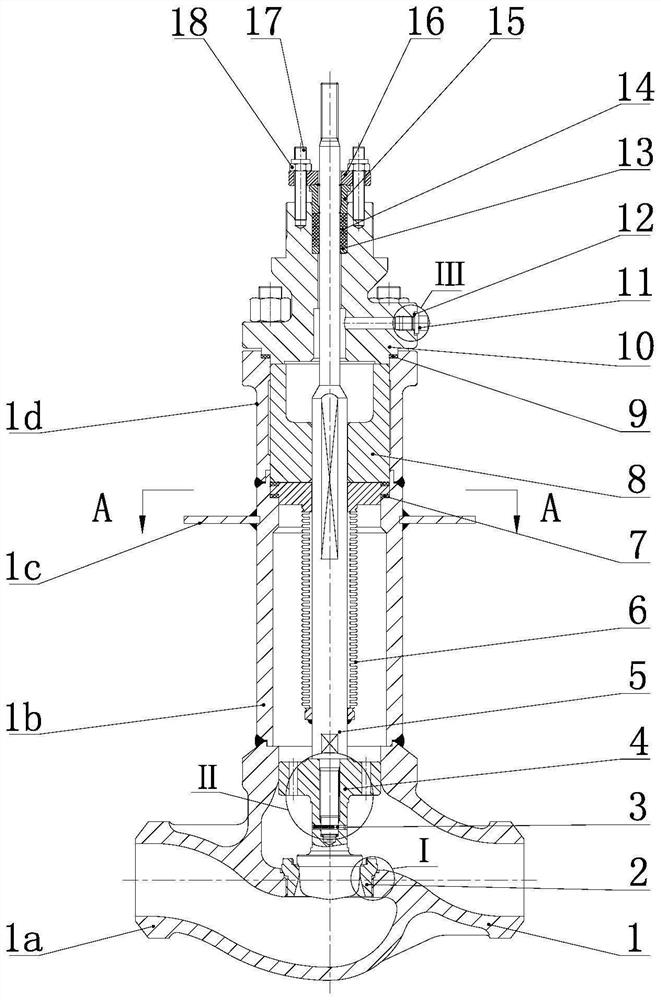
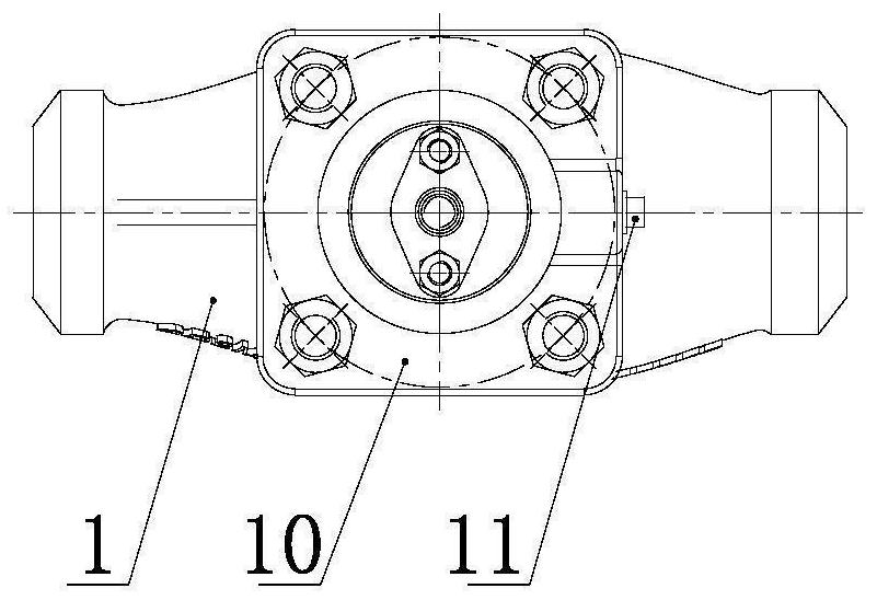
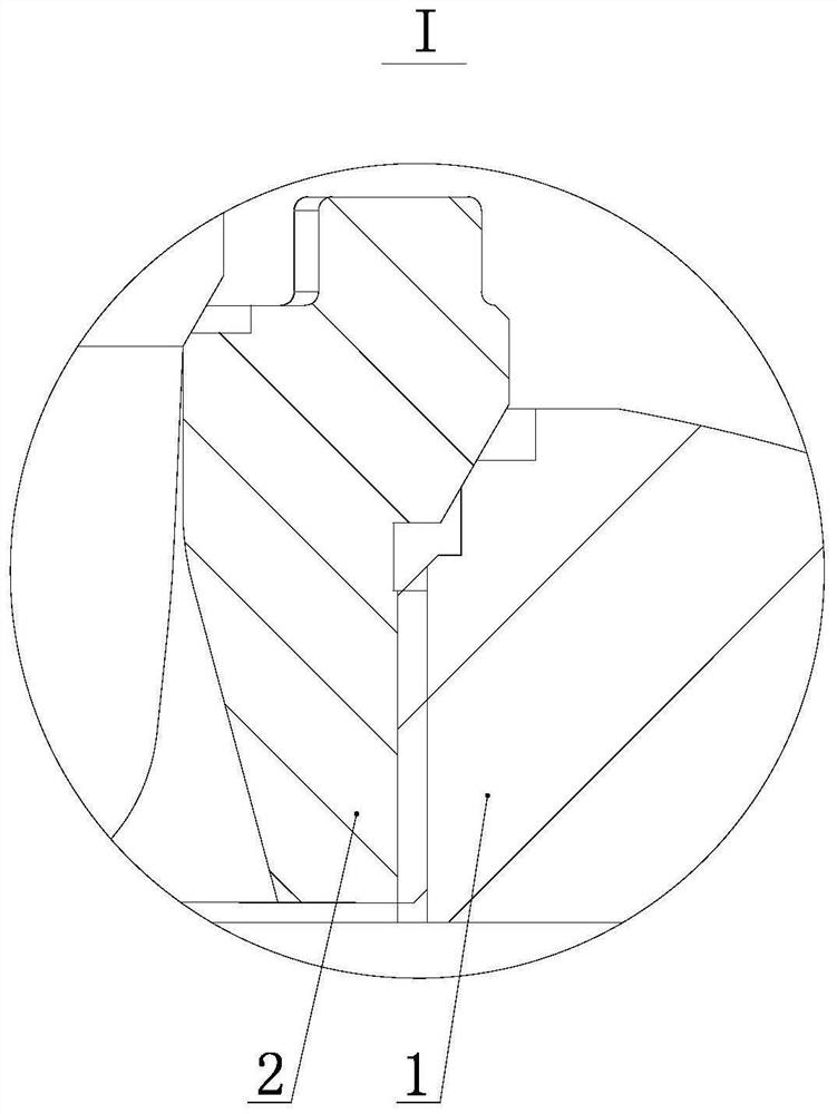
[0035] Such as Figure 1-Figure 3 As shown...


PUM


Abstract

The invention relates to a low-temperature regulating valve for isolating a pipeline, which comprises a valve body assembly, a valve seat is arranged at a throttling hole in a valve cavity of the valve body assembly, a valve core is arranged in the valve body assembly and is matched with the valve seat, the lower end of a valve rod is connected with the valve core, and the upper end of the valve rod penetrates through a corrugated pipe, a guide sleeve and an upper cover; the upper cover is pressed in an inner hole in the upper end of the valve body assembly; a valve body connecting pipe, an isolation drip tray and a valve body upper flange are sequentially arranged on the valve body, the upper end of the valve body is in matched positioning connection with a spigot at the lower end of the valve body connecting pipe, and the upper end of the valve body connecting pipe is in matched positioning connection with a spigot at the lower end of the valve body upper flange; the isolation drip tray is mounted and connected at the positioning seam allowance of the outer circle of the valve body connecting pipe and is used for preventing rainwater or condensate water from entering the isolation layer; the valve seat and the valve body assembly are sealed through the metal conical surface, and the leakage level can reach the V level or above; the valve core is in threaded connection with the valve rod, and the knurled pin is anti-loose and convenient to disassemble; the corrugated pipe and the filler are in dual sealing, sealing performance is good, and reliability is high.

Description

technical field [0001] The invention belongs to the technical field of valves, and relates to a low-temperature regulating valve for isolating pipelines. Background technique [0002] Cryogenic regulating valve is a regulating valve used in the working condition of low medium temperature (below -29°C), and is widely used in various devices such as liquefied natural gas, air separation, and oxygen production. [0003] At present, the cryogenic control valves of various domestic devices mainly rely on imports, but the procurement cycle of imported valves is long, the price is high, and maintenance is inconvenient. With the development of industrial technology in recent years, the demand for low-temperature control valves has increased, and the design and manufacturing technology of domestic low-temperature control valves has achieved a qualitative leap. Immature, resulting in insufficient market competitiveness. At present, the domestically produced cryogenic control valve m...

Claims


Application Information

Patent Timeline
Patent Type & Authority Applications(China)
IPC IPC(8): F16K1/04F16K1/32F16K1/42F16K1/48F16K1/50F16K27/02F16K41/10
CPCF16K1/04F16K1/32F16K1/422F16K1/48F16K1/50F16K41/10F16K27/02
Inventor 韩良云张程金响鸣陈杨
Owner JIANGSU INTELLIGENT SPECIAL VALVE CO LTD
Why Eureka
Try Eureka